
Reactivity controlling apparatus and fast reactor

a technology of reactivity control apparatus and fast reactor, which is applied in the direction of nuclear reactors, nuclear elements, greenhouse gas reduction, etc., to achieve the effects of suppressing reactivity, surplus reactivity, and high performance reactivity

Inactive Publication Date: 2009-07-09
KK TOSHIBA
View PDF2 Cites 4 Cited by
  • Summary
  • Abstract
  • Description
  • Claims
  • Application Information

AI Technical Summary

Benefits of technology

[0008]An object of the present invention is to provide a high performance reactivity control arrangement that suppresses the reactivity when the initial surplus reactivity is high, is compact and highly reliable and can realize a multiplexed reactor shutdown rod scram function by mean of simple and compact mechanisms.

Problems solved by technology

However, a reflector drive mechanism, an intra-reactor liquid level meter, an intra-reactor thermometer and other instruments are mounted in an upper part of a nuclear reactor, and hence such drive mechanisms need to be installed in a limited space.

Method used


Image

  • Reactivity controlling apparatus  and fast reactor
  • Reactivity controlling apparatus  and fast reactor
  • Reactivity controlling apparatus  and fast reactor

Examples


first embodiment

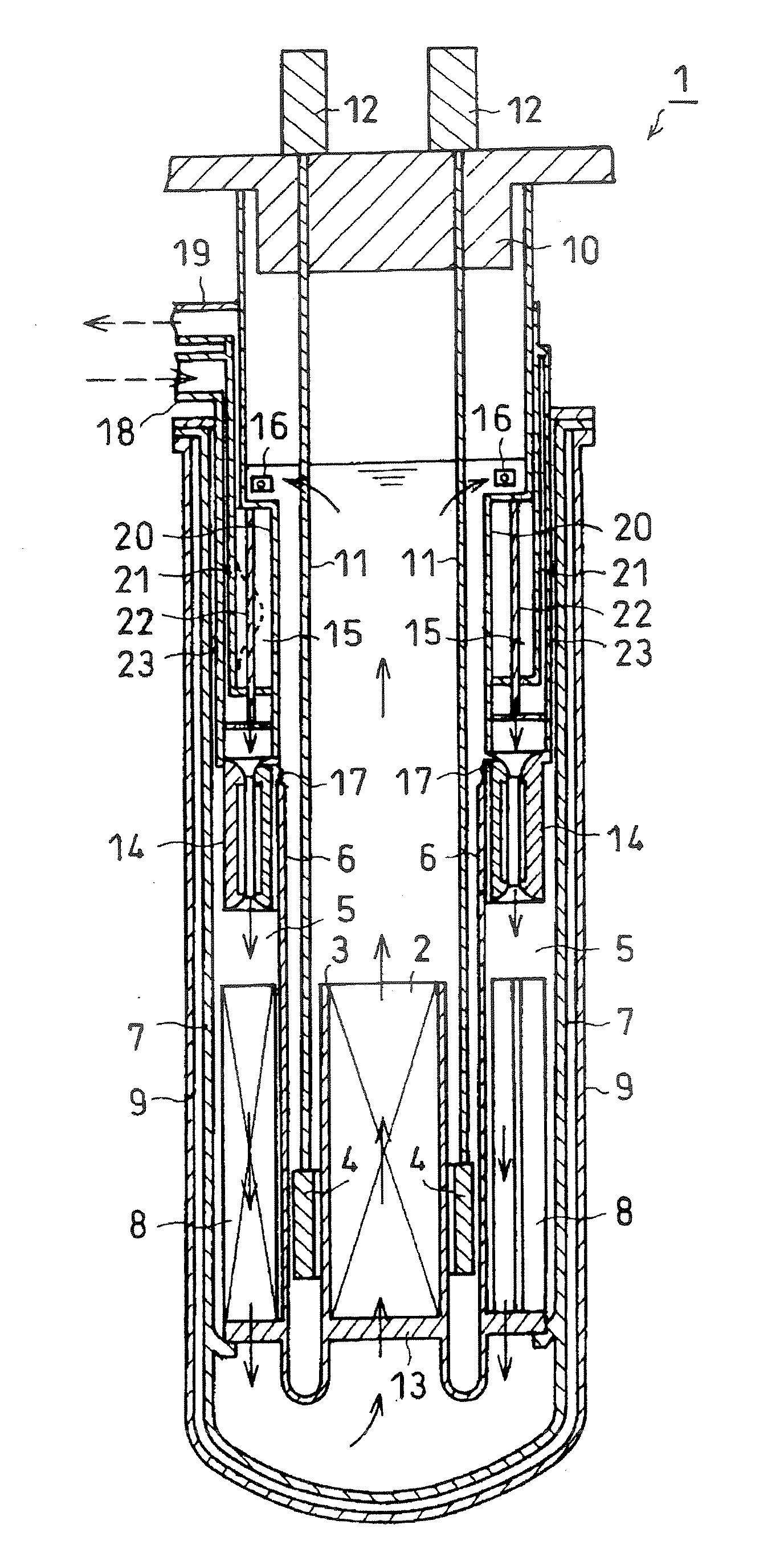
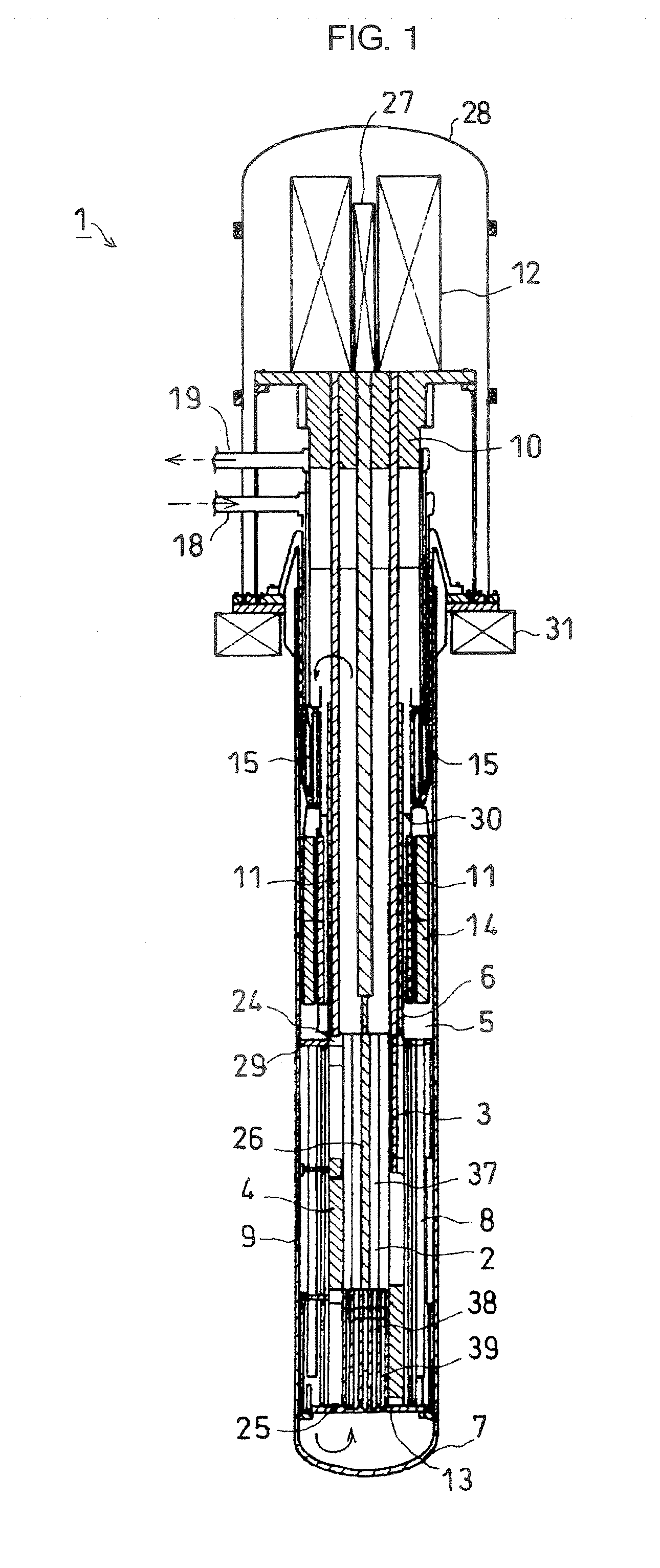
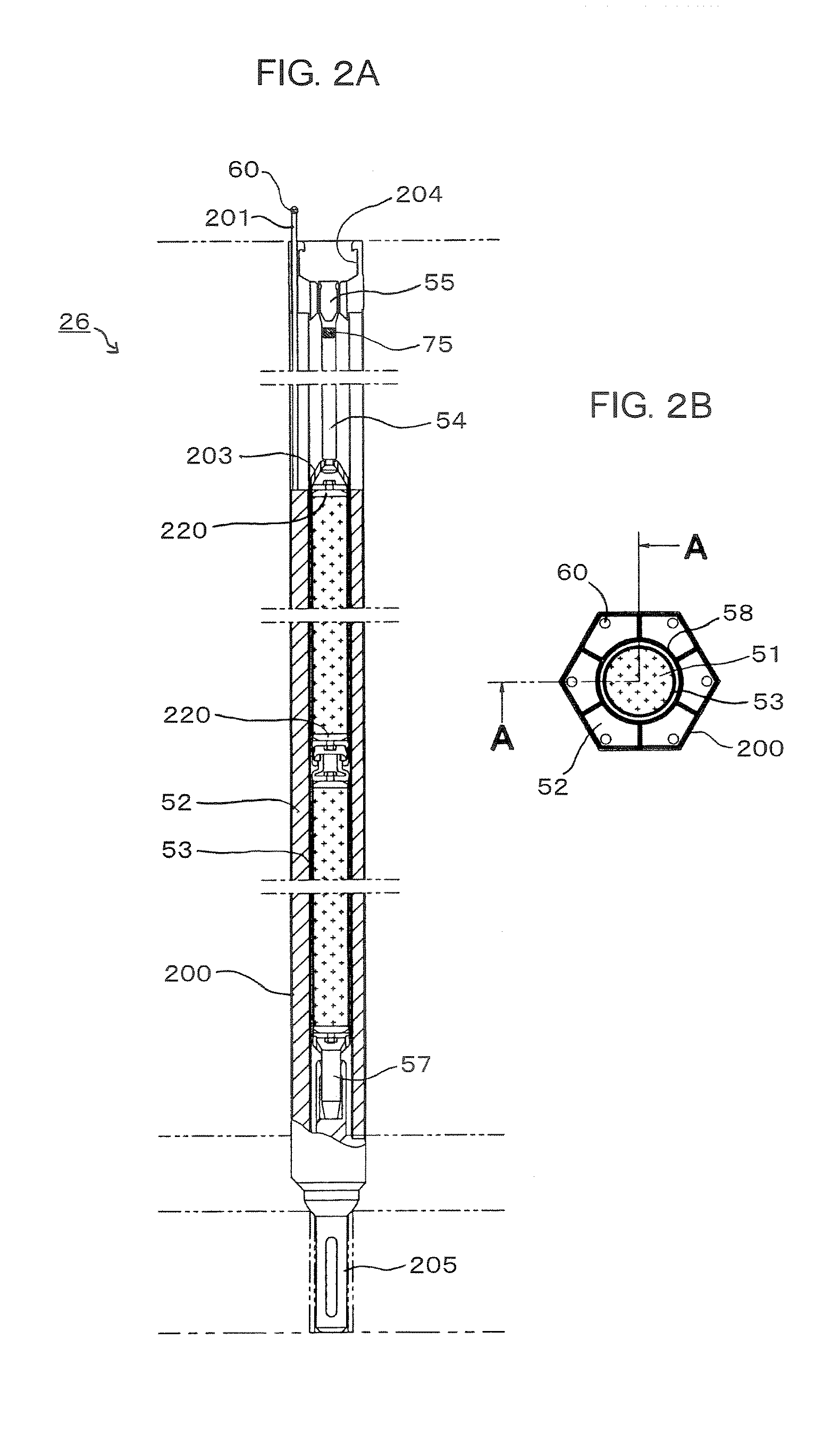
[0024]FIG. 1 is a schematic longitudinal cross sectional view of the first embodiment of fast reactor according to the present invention. FIGS. 2A and 2B schematically illustrate the configuration of the reactor shutdown rod in FIG. 1. FIG. 2A is a schematic lateral cross sectional view of the reactor shutdown rod taken along line A-A in FIG. 2B. FIG. 2B is a schematic transversal cross-sectional view thereof. FIG. 3 is an enlarged schematic longitudinal cross sectional view of the reactor shutdown rod drive mechanism of FIG. 1.

[0025]As shown in FIG. 1, the fast reactor 1 of this embodiment comprises as main component thereof a reactor core 2, a reactor core barrel 3, a plurality of reflectors 4, a bulkhead 6, a neutron shield 8, a reactor vessel 7, a plurality of fuel assemblies 37, an entrance module 38, a reactor core support plate 13, an upper support plate 29, an intermediate heat exchanger 15, an electromagnetic pump 14, a reactivity control assembly 26, an upper plug 10, a gu...

second embodiment

[0048]Now, the second embodiment of the present invention will be described below by referring to FIG. 6. The components of the second embodiment that are the same or similar to those of the first embodiment are denoted respectively by the same reference symbols and will not be described in detail any further.

[0049]A backup scram mechanism is provided to push down the rod 74 and release the pushdown armature 72 by means of a backup de-latching driving motor 73 of the reactor shutdown rod drive mechanism as shown in FIG. 5. On the other hand, in the second embodiment, the outer extension tube 67 is forcibly pushed up by a small stroke to close the latch finger 71 that has been grasping the reactor shutdown rod handling head 55 so as to allow the reactor shutdown rod 51 to make a freefall as shown in FIG. 6.

[0050]With the backup scram mechanism, the power cylinder 86 arranged at the extension tube latch mechanism 64 that is hanging up an upper part of the outer extension tube 67 pushe...

third embodiment

[0052]Now, the third embodiment of the present invention will be described below by referring to FIG. 7. The components of the third embodiment that are the same or similar to those of the first embodiment are denoted respectively by the same reference symbols and will not be described in detail any further.

[0053]As shown in FIG. 7, in the fast reactor 1 of this embodiment, the protection barrel 87 that covers the upper guide tube 66 of the reactor shutdown rod drive mechanism and the neutron absorbers 52 are provided at the lower end thereof with a rectifier plate 88 that operates as flow channel for coolant from the reactor core and secures a gap in order to accommodate the swell and expansion of the fuel assemblies 37 above the top level of the reactor core 2 so as to minimize the upward movement of the fuel assemblies 37 that can be produced by an earthquake.

[0054]When an earthquake occurs, both horizontal shakes and vertical shakes take place. As for vertical shakes, when the r...


PUM


Abstract

A fast reactor has a reactivity control assembly including a reactor shutdown rod of a backup reactor shutdown system and neutron absorbers to suppress the initial surplus reactivity, a reactor shutdown rod drive mechanism for releasing the reactor shutdown rod and units of neutron absorber drive mechanism capable of moving the respective neutron absorbers up and down. The reactor shutdown rod and the neutron absorbers are arranged in a wrapper tube. The reactor shutdown rod drive mechanism causes an inner extension tube to fall and release the reactor shutdown rod by means of a gripper section at the lowermost end of an outer extension tube by turning off the power supply to a holding magnet at the time of scram. Each of the units of neutron absorber drive mechanism has a dual tube type drive shaft including an outer extension shaft and an inner extension shaft. When grasping the neutron absorbers, the outer extension shaft is pulled up to allow both of the extension shafts to be inserted. After the outer extension tube gets to the handling head section of the neutron absorber, the outer extension shaft is pushed down to grasp the neutron absorber externally by means of the latch fingers of the gripper section thereof so that the neutron absorber can be moved up and down.

Description

CROSS REFERENCE TO RELATED APPLICATION[0001]This application is based upon and claims the benefit of priority from the prior Japanese Patent Application No. 2006-32308, filed on Feb. 9, 2006, the entire contents of which are incorporated herein by reference.BACKGROUND OF THE INVENTION[0002]The present invention relates to a reactivity control arrangement and a fast reactor utilizing the same.[0003]Japanese Patent No. 3126524 (Patent Document 1) discloses a known fast reactor (entire contents of which are incorporated herein by reference). Referring to FIG. 10 of the accompanying drawings, the known fast reactor comprises a reactor core 2 that has nuclear fuel assemblies. The reactor core 2 shows a substantially cylindrical profile and a core barrel 3 is arranged around the outer periphery of the reactor core 2 in order to protect the reactor core 2. A circular-shaped annular reflector 4 is so provided around the core barrel 3 as to surround the core barrel 3. A bulkhead 6 is arrange...

Claims


Application Information

Patent Timeline
IPC IPC(8): G21C7/10G21C7/28G21C1/02
CPCG21C1/02G21C7/10Y02E30/39Y02E30/34G21C7/28Y02E30/30
Inventor SUZUKI, TOSHIYUKIMATSUMOTO, KOJIKOIZUMI, KENZOTSUBOI, YASUSHI
Owner KK TOSHIBA
Learn More