Photonic Integrated Circuits having Chirped Elements

Inactive Publication Date: 2009-07-09
INFINERA CORP
View PDF9 Cites 4 Cited by
  • Summary
  • Abstract
  • Description
  • Claims
  • Application Information

AI Technical Summary

Problems solved by technology

Due to systematic variations, as well as process variations, optical signals output from the PIC may have undesirable optical characteristics.
For example, the power levels of one or more optical signals output from the PIC may be too low or too high, resulting in an inadequate signal quality.
Conventionally, such characteristics may be improved by providing additional control circuitry on the PIC, but at the expense of decreased yields, and increased complexity and cost.

Method used


Image

  • Photonic Integrated Circuits having Chirped Elements
  • Photonic Integrated Circuits having Chirped Elements
  • Photonic Integrated Circuits having Chirped Elements

Examples


Embodiment Construction

Background of the Invention

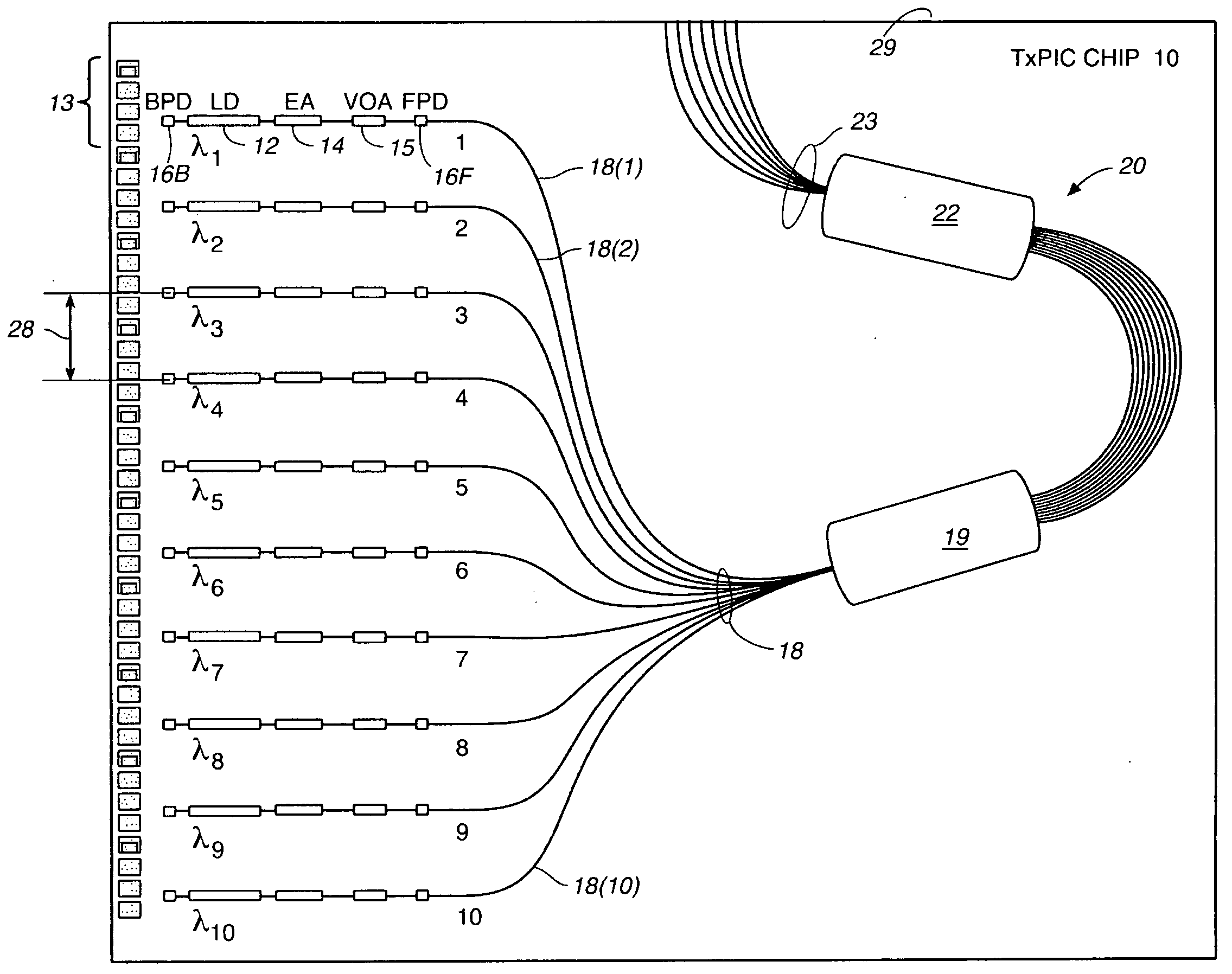
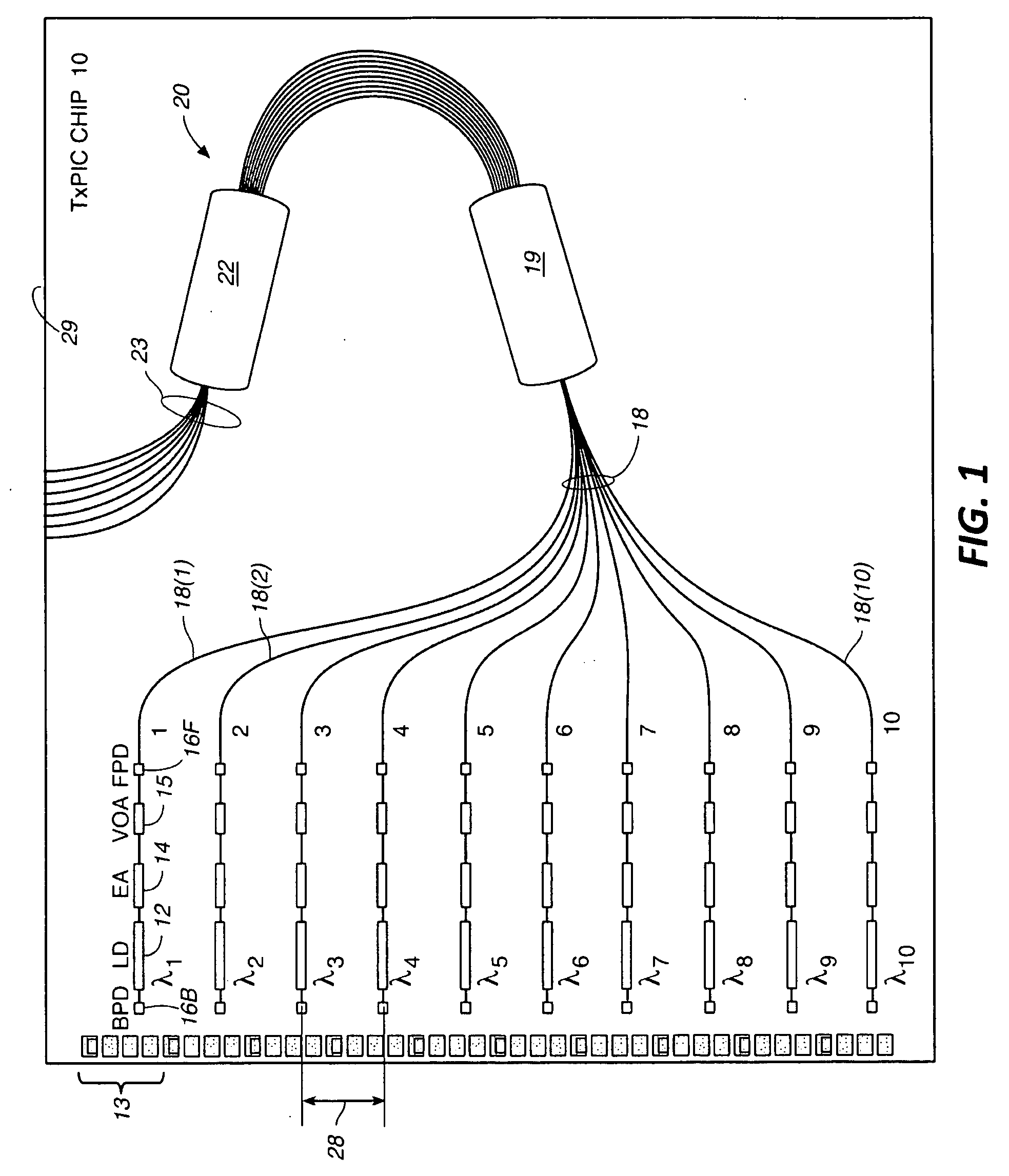
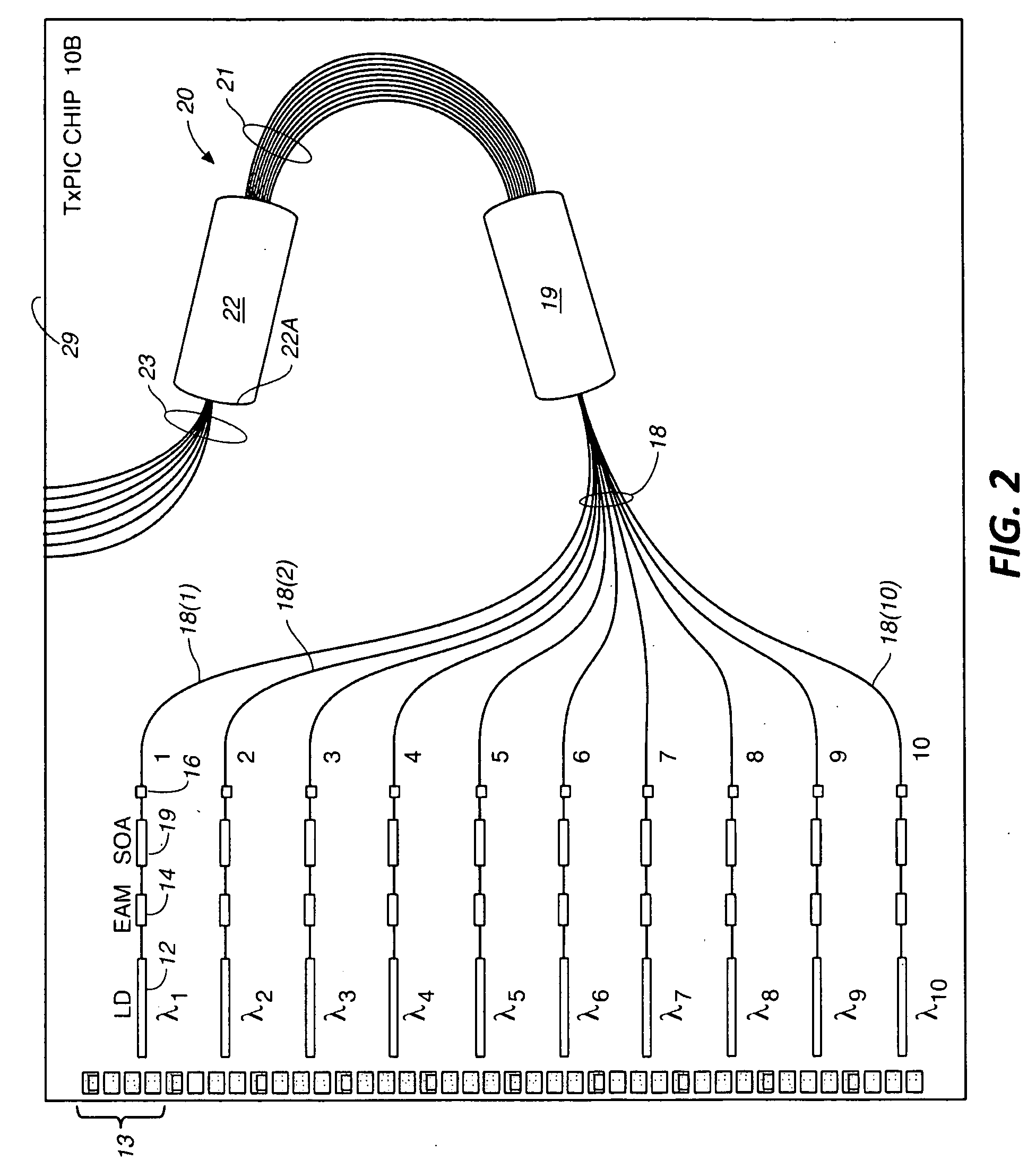
[0002]Wavelength division multiplexed (WDM) optical communication systems are known in which multiple optical signals, each having a different wavelength, are combined onto an optical fiber, for example. Such systems often include discrete optical components, such as lasers, modulators, combiners that generate and multiplex the optical signals. More recently, photonic integrated circuits have been developed in which these components have been integrated onto a common substrate.

[0003]For example, conventional photonic integrated circuits may include a plurality of lasers, such as distributed feedback (DFB) lasers, which output optical signals that are modulated and / or attenuated by other components provided on a substrate and then combined by an optical combiner into a WDM signal. Due to systematic variations, as well as process variations, optical signals output from the PIC may have undesirable optical characteristics. For example, the power levels of one...


PUM


Abstract

Consistent with the present disclosure, optical devices are provided along different optical paths in a photonic integrated circuit (PIC). The optical components have different optical losses associated therewith so that optical signals propagating in the optical paths have desired power levels, which may be uniform, for example.

Description

[0001]This application is a continuation-in-part of U.S. patent application Ser. No. 11 / 556,278, which is a divisional of U.S. application Ser. No. 11 / 268,325, which is a continuation-in-part of U.S. patent application Ser. No. 10 / 267,331, filed Oct. 8, 2002 and entitled, TRANSMITTER PHOTONIC INTEGRATED CIRCUITS (TxPIC) AND OPTICAL TRANSPORT NETWORKS EMPLOYING TxPICs, also published on May 22, 2003 as Pub. No. US2003 / 0095737 A1; U.S. patent application Ser. No. 10 / 267,330, filed Oct. 8, 2002 and entitled, TRANSMITTER PHOTONIC INTEGRATED CIRCUIT (TxPIC) CHIP ARCHITECTURES AND DRIVING SYSTEMS AND WAVELENGTH STABILIZATION FOR TxPICs, also published on May 22, 2003 as Pub. No. US2003 / 0095736 A1; and U.S. patent application Ser. No. 10 / 267,304, filed Oct. 8, 2002 and entitled, AN OPTICAL SIGNAL RECEIVER PHOTONIC INTEGRATED CIRCUIT (RxPIC), AN ASSOCIATED OPTICAL SIGNAL TRANSMITTER PHOTONIC INTEGRATED CIRCUIT (TxPIC) AND AN OPTICAL TRANSPORT NETWORK UTILIZING THESE CIRCUITS, also published...

Claims


Application Information

Patent Timeline
IPC IPC(8): G02B6/12
CPCG02B6/12004G02B6/12019G02B6/4249H04J14/02H01S5/0268H01S5/4087H01S5/02248H01S5/02325
Inventor KISH, JR., FRED A.ZIARI, MEHRDADNAGARAJAN, RADHAKRISHNAN L.KATO, MASAKIDOMINIC, VINCENT G.MURTHY, SANJEEVNILSSON, ALAN
Owner INFINERA CORP
Why Eureka
Try Eureka