
Radiation Detector Assembly, Radiation Detector, and Method for Radiation Detection

a radiation detector and assembly technology, applied in the direction of x/gamma/cosmic radiation measurement, instruments, semiconductor devices, etc., can solve the problems of reducing the detection efficiency of high-energy gamma rays, affecting the detection accuracy of gamma ray detection, etc., to achieve the effect of improving the detection capability

Active Publication Date: 2009-07-16
KONINKLJIJKE PHILIPS NV
View PDF10 Cites 72 Cited by
  • Summary
  • Abstract
  • Description
  • Claims
  • Application Information

AI Technical Summary

Benefits of technology

[0023]It is, therefore, one aspect of the invention to provide a radiation detector that provides improved detection capabilities.

Problems solved by technology

Efficient detection of higher energy gammas (e.g., with energy above 300 keV) with low Z materials requires detectors of large size, which is an unattractive property for size-sensitive applications.
As an example, lead-glass (a scintillator) has a very low light output, which impedes a photomultiplier's ability to convert the light emitted by lead-glass into electrical signals.
As a result of the low mobility-lifetime product, direct-detection solid-state devices made of lead sulfide are not easily fabricated in configurations that efficiently detect high energy gamma rays.
One problem with sandwich detectors is that it is extraordinarily difficult to determine how many of the secondary charged particles created within the high-Z layer escaped that layer and entered the low-Z layer.
As a result, these sandwich detectors have poor accuracy in characterizing the energy of the gamma-ray that was originally incident on the planar high-Z layer.
This inaccuracy leads to poor energy resolution in many instances.

Method used


Image

  • Radiation Detector Assembly, Radiation Detector, and Method for Radiation Detection
  • Radiation Detector Assembly, Radiation Detector, and Method for Radiation Detection
  • Radiation Detector Assembly, Radiation Detector, and Method for Radiation Detection

Examples


Embodiment Construction

[0043]While specific embodiments of the radiation detector of the invention are described below, the discussion is not intended to be limiting of the invention. To the contrary, the description of specific embodiments is intended to illustrate the broad scope of the invention. As a result, any discussion of particular embodiments is intended to be exemplary only. It is understood that those skilled in the art may appreciate variations and equivalents of the embodiments described herein. Those variations and equivalents are intended to be encompassed by the scope of the invention.

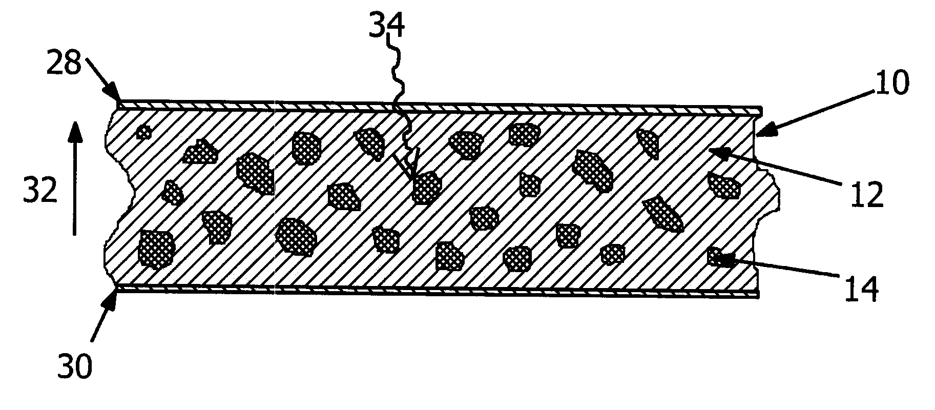
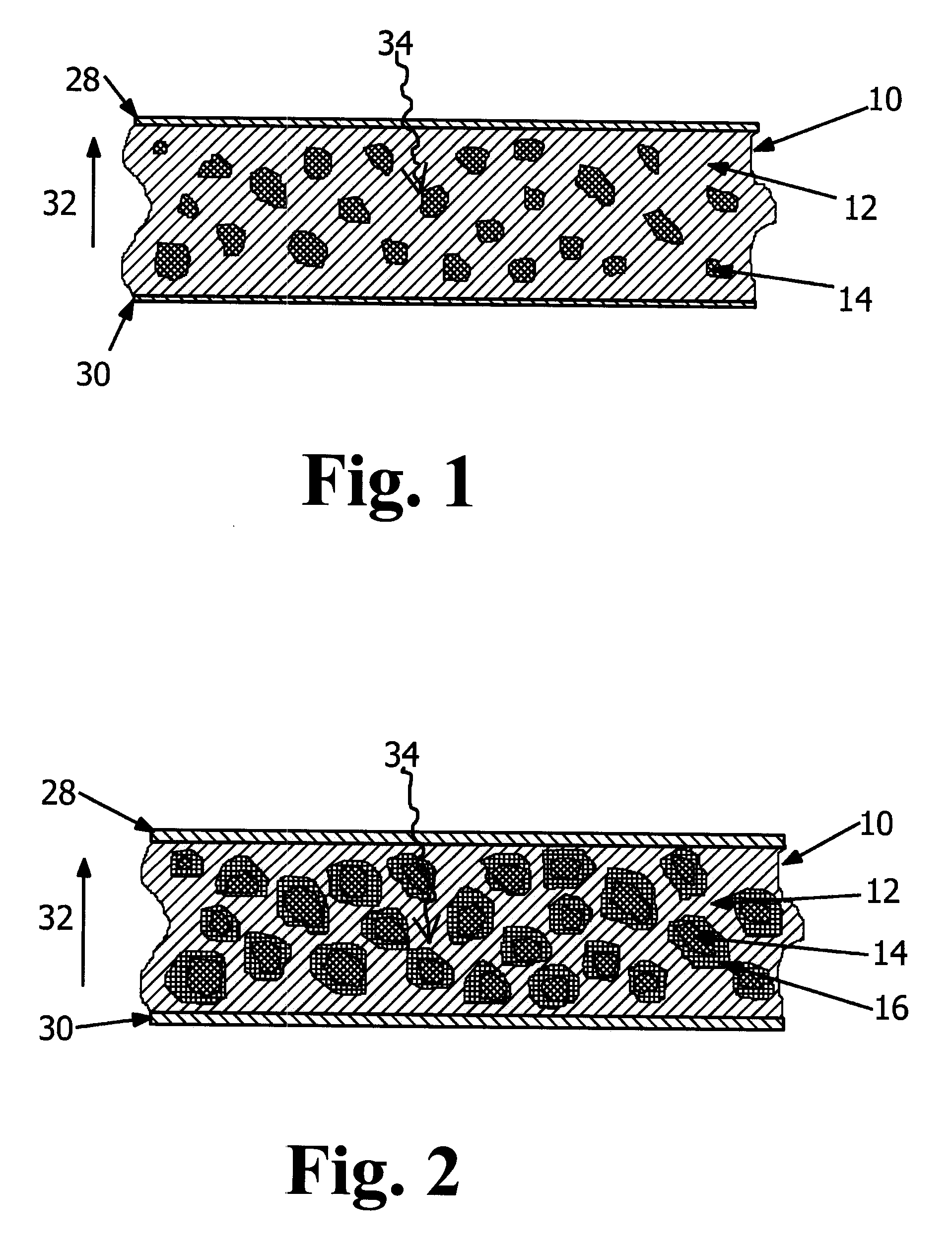
[0044]FIG. 1 provides a partial cross-sectional side view of one composite layer 10 contemplated for use within the radiation detector of the invention. The composite layer 10 includes a composite material consisting of a host matrix 12 of a semiconducting polymer (such as plastic), in which nanoparticles 14 are embedded.

[0045]A nanoparticle 14 is defined, inter alia, as a sufficiently small quantity of a ma...


PUM


Abstract

An assembly for detecting radiation is described. The assembly includes a host matrix with particles suspended within the host matrix. The particles are capable of generating a charge carrier upon interaction with the radiation. A first electrode is disposed adjacent to a first surface of the host matrix, and a second electrode disposed adjacent to a second surface of the host matrix. A power source operatively connects to one of the first or second electrodes. The power source establishes an electric field between the first and second electrodes such that a ratio of a mobility-lifetime-field strength product of the charge carrier to the thickness of the host matrix is greater than or equal to 0.1. A radiation detector and a method for detecting radiation are also described.

Description

CROSS-REFERENCE TO RELATED APPLICATIONS[0001]This application relies for priority on U.S. Provisional Patent Application Ser. No. 61 / 010,929, filed on Jan. 14, 2008, the contents of which are incorporated herein by reference.FIELD OF INVENTION[0002]This disclosure concerns an apparatus and a method for radiation detection. More specifically, this disclosure describes a semiconductor type composite material useable for radiation detection and a method of use of that material.DISCUSSION OF RELATED ART[0003]As should be apparent to those skilled in the art, ionizing radiation interacts with matter in several ways. Among the different ways in which ionizing radiation interacts with matter, there are three of particular note: (1) Compton scattering, (2) photo-electric absorption, and (3) pair production. In the case of Compton scattering, ionizing radiation is converted into a charged and a neutral particle. For example, an impingent gamma photon may be converted into an electron and a l...

Claims


Application Information

Patent Timeline
IPC IPC(8): G01T1/24
CPCG01T1/16G01T1/242G01T3/08G01T1/24
Inventor WEINBERG, IRVING
Owner KONINKLJIJKE PHILIPS NV
Learn More