Drive Unit and Image Forming Apparatus Equipped with the Same

a technology of drive unit and image forming apparatus, which is applied in the direction of mechanical energy handling, electrographic process, instruments, etc., can solve the problems of difficult adjustment of the gap between the encoder and the sensor, poor assembly operability, and reading defects of the sensor, so as to prevent the adhesion of foreign matter, easy to produce, and low cost

Active Publication Date: 2009-07-16
KYOCERA DOCUMENT SOLUTIONS INC
View PDF3 Cites 21 Cited by
  • Summary
  • Abstract
  • Description
  • Claims
  • Application Information

AI Technical Summary

Benefits of technology

[0009]In view of the above problems, it is an object of the present invention to provide a drive unit which is capable of preventing the adhesion of foreign matters to an encoder and a sensor, is also effective for the tilt of an output shaft, and can be produced easily at low cost, and an image forming apparatus using the drive unit.

Problems solved by technology

Therefore, there is a fear in that foreign matters such as lubricating oil and abrasion powder may adhere to an encoder and a sensor to cause a reading defect of the sensor.
Further, the setting space in a direction of the rotation shaft is also required, and hence assembly operability is poor.
Further, because the encoder and the sensor are fixed, it is difficult to adjust the gap between the encoder and the sensor.
For example, in the case where the members to be rotated are rotated while the encoder and the sensor are in contact with each other, there is a problem in that abrasion of the encoder may occur.
Therefore, the intervals between the support bearings are short, and the tilt of the output shaft may be increased depending on the size error of the support positions of the bearings.
Further, the housing is separated into a first member and a second member, and hence it is necessary to enhance a molding precision of the housing as well as an alignment precision, which is inconvenient in terms of production and cost.

Method used


Image

  • Drive Unit and Image Forming Apparatus Equipped with the Same
  • Drive Unit and Image Forming Apparatus Equipped with the Same
  • Drive Unit and Image Forming Apparatus Equipped with the Same

Examples


Embodiment Construction

[0038]Reference will now be made in detail to various embodiments of the invention, one or more examples of which are illustrated in the accompanying drawings. Each example is provided by way of explanation of the invention, and by no way limiting the present invention. In fact, it will be apparent to those skilled in the art that various modifications, combinations, additions, deletions and variations can be made with respect to these described embodiments without departing from the scope or spirit of the present invention. For instance, features illustrated or describe as part of one embodiment can be used in another embodiment to yield a still further embodiment. It is intended that the present invention encompass such modifications, combinations, additions, deletions, applications and variations that come with in the scope of the appended claims.

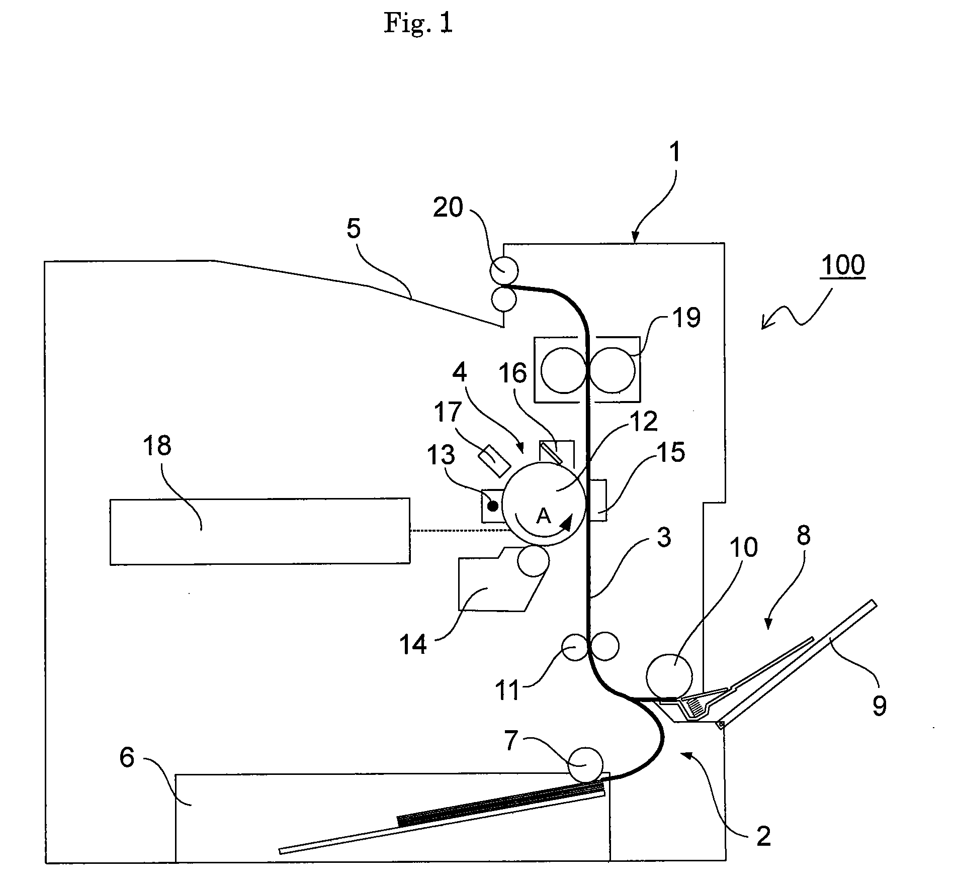
[0039]FIG. 1 is a schematic view illustrating an entire configuration of an image forming apparatus with a drive unit of the present in...


PUM


Abstract

A drive unit includes a motor being a drive source, a velocity reduction gear for reducing the revolution of the motor, an output shaft for connecting the velocity reduction gear to the rotation shaft of a photosensitive drum, and a velocity detection mechanism including an encoder and sensor members and detecting the revolution of the output shaft. The velocity reduction gear and the velocity detection mechanism are placed in a unit housing including a housing body made of a resin with one end opened and a support plate made of metal closing the opening of the housing body, and the output shaft is rotatably supported by the housing body and the support plate.

Description

INCORPORATION BY REFERENCE[0001]This application is based upon and claims the benefit of priority from the corresponding Japanese Patent Application No. 2008-006394, filed Jan. 16, 2008, the entire contents of which is incorporated herein by reference.FIELD OF THE INVENTION[0002]The present invention pertains to a drive unit capable of driving a rotation member and detecting and controlling the rotations thereof.BACKGROUND OF THE INVENTION[0003]In image forming apparatuses such as a copying machine, a printer, a facsimile, and the like, various members to be rotated are used for image forming processing. For example, in an image forming portion of an electrophotographic system, a photosensitive drum is placed, and rotation members such as a transfer roller and a cleaning roller are provided in contact with the surface of the photosensitive drum. The photosensitive drum and the members to be rotated are rotatably driven at a predetermined velocity (rpm), and an image is formed throug...

Claims


Application Information

Patent Timeline
Patent Type & Authority Applications(United States)
IPC IPC(8): H02K11/00H02K7/14
CPCG03G15/757H02K11/0026H02K7/116H02K5/08H02K11/22
Inventor OMURA, HIROYOSHISHIMOHORA, YUUYA
Owner KYOCERA DOCUMENT SOLUTIONS INC
Why Eureka
Try Eureka