Power Supply System, Vehicle with the Same and Temperature Managing Method
Active Publication Date: 2009-07-16
TOYOTA JIDOSHA KK
View PDF5 Cites 54 Cited by
Summary
Abstract
Description
Claims
Application Information
AI Technical Summary
This helps you quickly interpret patents by identifying the three key elements:
Problems solved by technology
Method used
Benefits of technology
[0027]According to the invention, the temperature of the battery unit can be appropriately man
Problems solved by technology
Therefore, charge/discharge characteristics thereof are liable to be affected by a temperature.
In general, charge/discharge performance of the chemical cell lowers with lowering in temperature, but a higher temperature may promote deterioration of the chemical cell.
In particular, a quantity of the reaction heat is relatively large in a lithium ion battery and the like.
Therefore, sufficient temperature management cannot
Method used
Image
Click on the blue label to locate the original text in one second.
Reading with bidirectional positioning of images and text.
Examples
first modification
[0131](First Modification)
[0132]Power supply system 1 according to the embodiment of the invention already described can implement both the control of battery current Ib1 of converter CONV1 that is the temperature management target and the control of the power supplied to drive power generating unit 3. Since the electric power supplied to drive power generating unit 3 corresponds to the sum of the power provided from converters CONV1 and CONV2, the power supplied to drive power generating unit 3 and the power provided from converter CONV2 can be controlled to control indirectly battery current Ib1, i.e., the power passing through converter CONV1 that corresponds the temperature management target.
[0133]Accordingly, a first modification of the embodiment of the invention will now be discussed in connection with a configuration which controls battery current Ib2 of converter CONV2 that is not the temperature management target, and thereby indirectly controls battery current Ib1 of conv...
first embodiment
[0167]The first modification of the embodiment of the invention can achieve substantially the same effect as the invention already described. Further, the first modification of the embodiment of the invention produces the switching instruction for converter CONV2 that cooperates to perform the power supply with converter CONV1 corresponding to battery unit BAT1 of the temperature management target, and particularly produces the switching instruction corresponding to the power request made by the load device. Therefore, it is possible to respond more reliably to the power request from the load device, as compared with the embodiment of the invention.
second modification
[0168](Second Modification)
[0169]In addition to the power supply system having the two battery units as described before, the invention may be applied to a power supply system having three or more battery units.
[0170]Referring to FIG. 11, description will now be given on the schematic structure showing a substantial part of a vehicle 100# provided with a power supply system #1 according to a second modification of the embodiment of the invention.
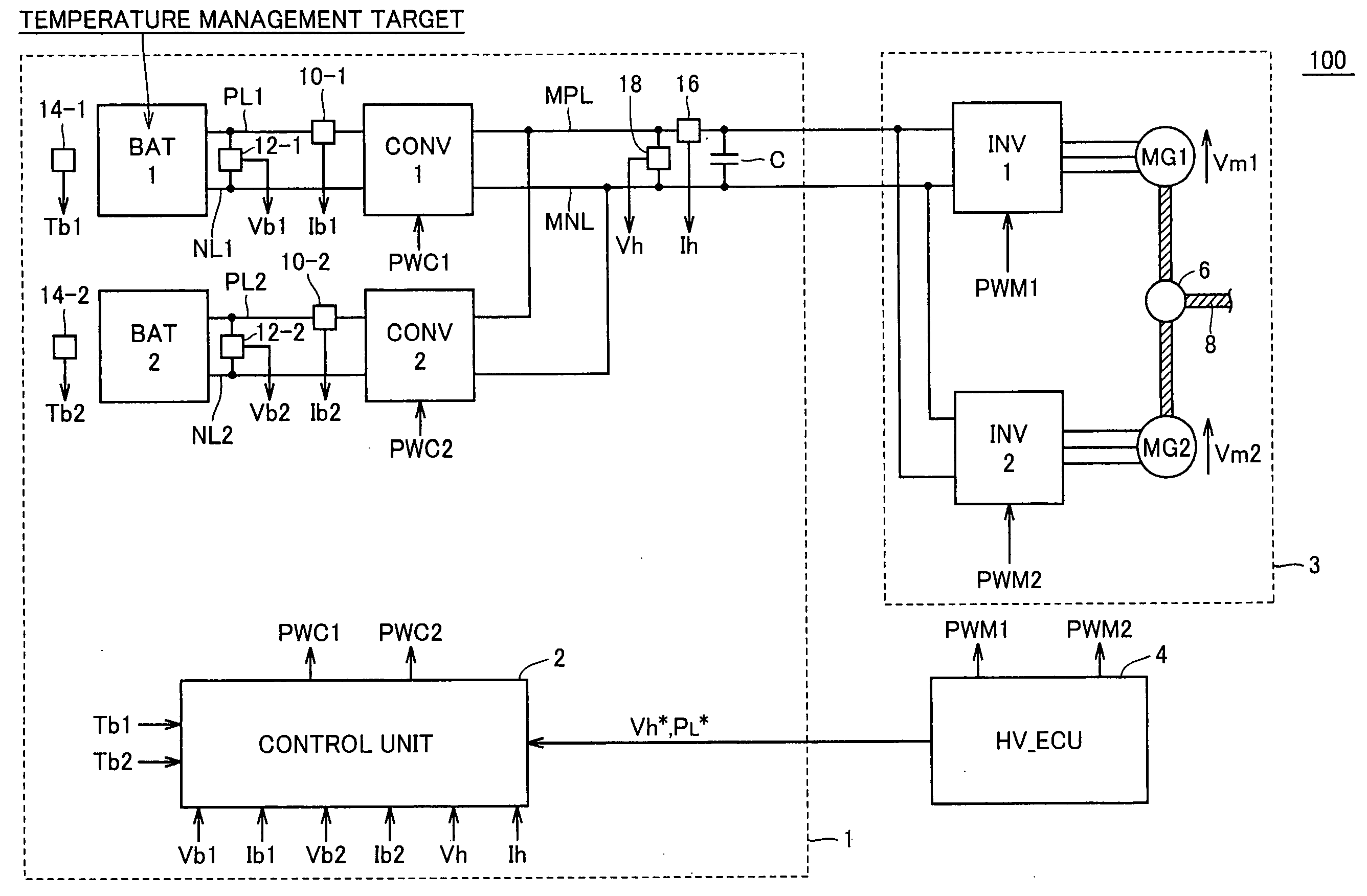
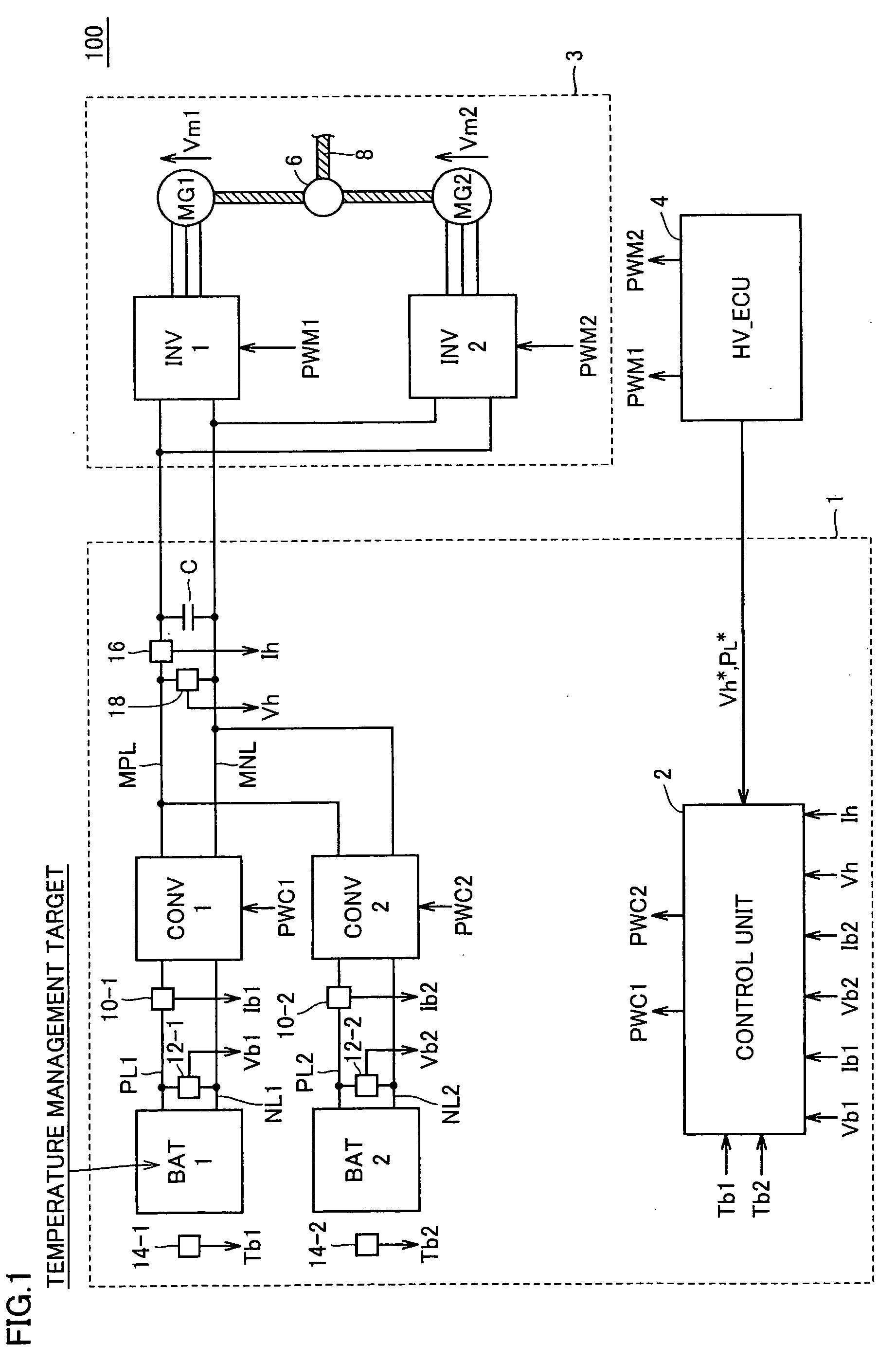
[0171]Vehicle 100# employs a power supply system 1# instead of power supply system 1 in vehicle 100 shown in FIG. 1. Drive power generating unit 3 and HV_ECU 4 in vehicle 100# are substantially the same as those in FIG. 1, and therefore detailed description thereof is not repeated.
[0172]Power supply system 1# includes a first group power supply unit 200A that includes N sets of converters CONV1 and corresponding battery units BAT1 that are the same as those employed in power supply system 1 in FIG. 1, and also includes a second group power s...
PUM
Abstract
A request determining unit compares a battery temperature of a battery unit with a predetermined temperature management value, and produces a heating request or a cooling request when a temperature deviation of a predetermined threshold is present between them. A current direction determining unit determines, based on thermal reaction characteristics of the battery unit, in which one of a direction on a charge side and a direction on a discharge side a current is to be passed for responding to the heating request or the cooling request. A target current value determining unit determines a target current value related to the charge/discharge determined by the current direction determining unit. A current control unit produces a switching instruction for matching a battery current of the battery unit with the target current value provided from a selecting unit.
Description
TECHNICAL FIELD[0001]The invention relates to a power supply system having a plurality of battery units, a vehicle provided with the same and a temperature managing method, and particularly to a technique that implements temperature management of the battery device including a chemical cell while suppressing an influence on supply / reception of an electric power to / from a load device.BACKGROUND ART[0002]In recent years, attention has been given to vehicles such as a electric vehicle, a hybrid vehicle, a fuel-cell electric vehicle that use an electric motor as a drive power source in view of environmental issues. This kind of vehicle employs a rechargeable and dischargeable battery unit for supplying an electric power to an electric motor and for converting a kinetic energy into an electric energy for storage during a regenerative operation.[0003]For improving drive performance such as acceleration performance and a continuous travel distance of the vehicle using the electric motor as...
Claims
Application Information
Patent Timeline
Application Date:The date an application was filed.
Publication Date:The date a patent or application was officially published.
First Publication Date:The earliest publication date of a patent with the same application number.
Issue Date:Publication date of the patent grant document.
PCT Entry Date:The Entry date of PCT National Phase.
Estimated Expiry Date:The statutory expiry date of a patent right according to the Patent Law, and it is the longest term of protection that the patent right can achieve without the termination of the patent right due to other reasons(Term extension factor has been taken into account ).
Invalid Date:Actual expiry date is based on effective date or publication date of legal transaction data of invalid patent.