Electronic security seal and system

a technology electronic signals, applied in the field of electronic security seals, can solve the problems of long time, inability to catch perpetrators, not even to identify, and simultaneous reception of multiple potentially overlapping and garbled messages by a single interrogator, so as to increase functionality and utility, increase security and reliability, and increase simplicity in construction and use.

a technology electronic signals, applied in the field of electronic security seals, can solve the problems of long time, inability to catch perpetrators, not even to identify, and simultaneous reception of multiple potentially overlapping and garbled messages by a single interrogator, so as to increase functionality and utility, increase security and reliability, and increase simplicity in construction and use.

US20090179757A1Inactive Publication Date: 2009-07-16COHN ODED YAIR +1

Image

  • Electronic security seal and system
  • Electronic security seal and system
  • Electronic security seal and system

Examples


Embodiment Construction

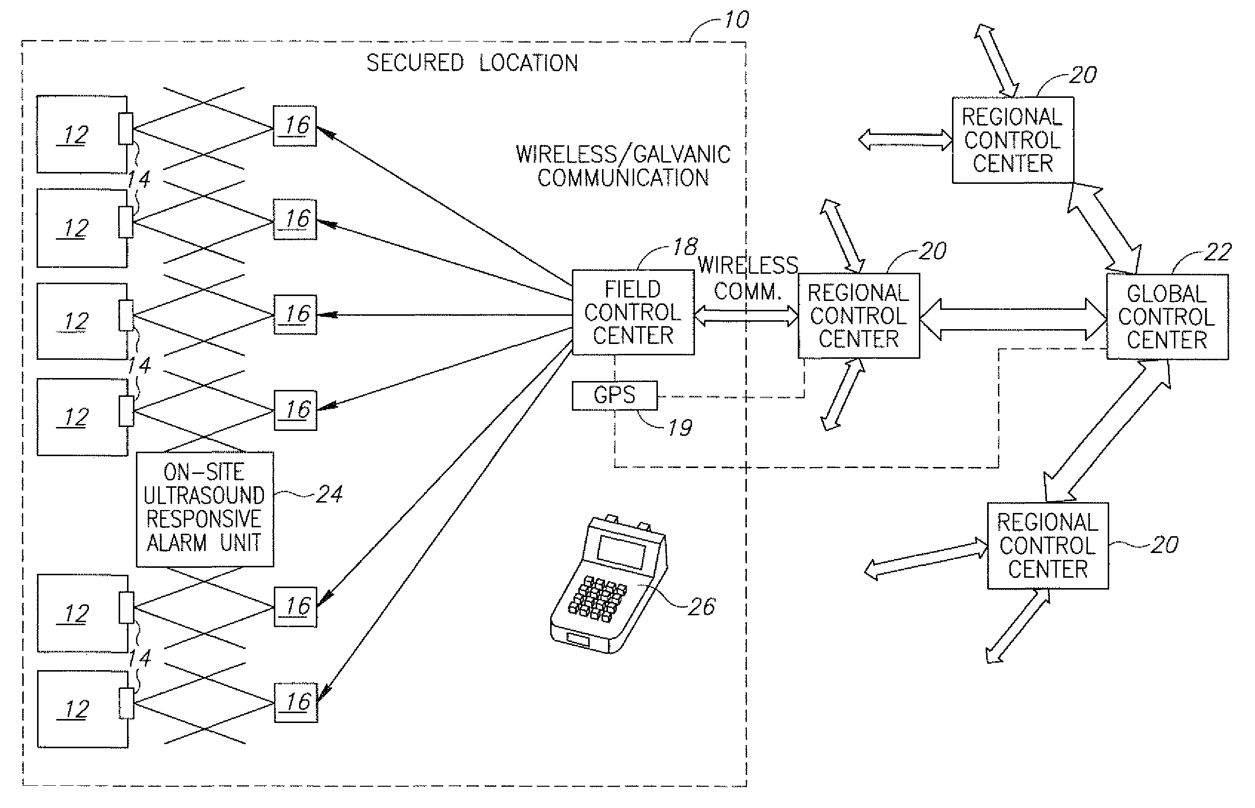
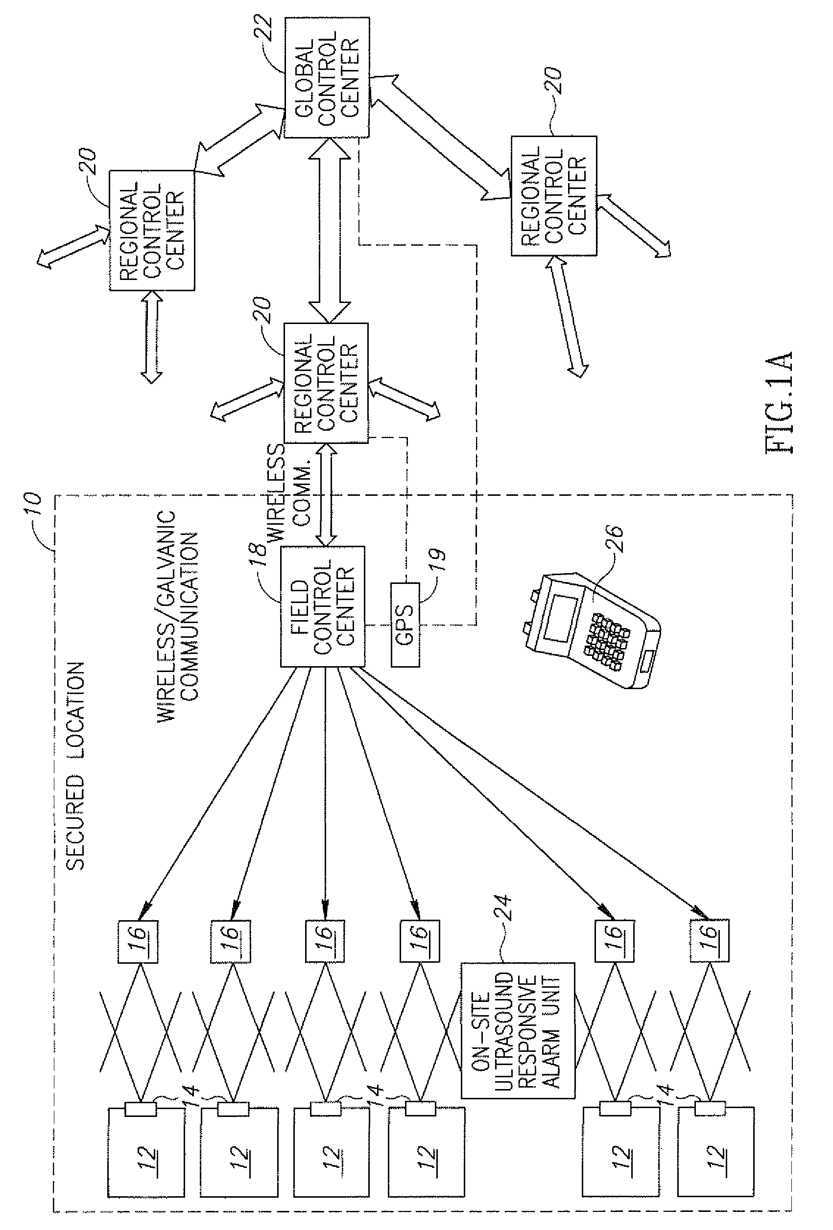
[0096]Referring now to FIG. 1A, the present invention provides a hierarchical security system for the protection, monitoring and tracking of the status and spatial position of cargo containers 12 at a secured location, referenced generally 10, constructed and operative in accordance with a preferred embodiment of the present invention.

[0097]The system employs an electronic security seal 14 for mechanically preventing the pilfering of the contents of a cargo container and further for emitting an alarm signal in response to an attempt to pilfer the contents. The security seal 14 also has an electronic memory which may be preprogrammed to contain details of the bill of lading, container identity, full cargo details, location, and other useful information. Seal 14 is described further in detail, hereinbelow.

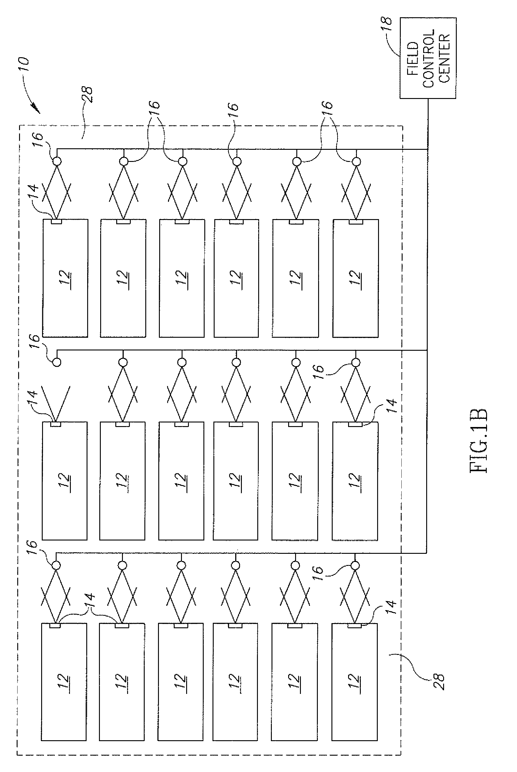
[0098]The system of the invention also includes a plurality of stationary terminals 16 at selected positions within the secured location. The stationary terminals 16 are arranged for...


PUM


Abstract

A tamper-proof electronic security seal which includes a bolt and a locking element and an electronic seal element. The bolt has a head and a hollow shank extending therefrom having a longitudinal bore formed therein. The shank is dimensioned to pass through a lock hasp and has a free end formed for locking engagement with the locking element. The electronic seal element is formed for mechanical connection to the bolt head, and includes an electrical power source, a control unit, communications means responsive to the control unit and a sensor adapted for insertion into the longitudinal bore of the shank, and connected to the control unit. In response to a severing of the shank and the sensor inserted therein, the control unit is operative to activate the communications means to emit an alarm signal.

Description

FIELD OF THE INVENTION[0001]The present invention relates to security seals for cargo containers and the like, and particularly to smart seals and cargo security systems.BACKGROUND OF THE INVENTION[0002]It is well known to secure cargo containers by the use of mechanical seals. The purpose of using seals is two fold, namely, to prevent, or at least render difficult, breaking into cargo containers, and to make sure that any such attempts do not go undetected.[0003]The simplest type of such mechanical seals includes a steel bolt composed of a shank with a shank head formed at one end and a free end adapted for locking engagement with a locking element. A typical PRIOR ART seal is seen in FIG. 2. In use, the bolt is positioned so as to pass through the hasp of a container locking mechanism, thereby to prevent opening of the locking mechanism without breaking the seal. Over the years, such seals have become increasingly sophisticated, and have advanced so as to include means for indicat...

Claims


Application Information

Patent Timeline
16 Jul 2009
Publication
US20090179757A1
IPC
E05B45/06
CPC
G09F3/0376
Inventors
COHN, ODED YAIR; BEN SHALOM, ZVI