Optical storage interface apparatus, method of controlling an optical storage interface

a technology of optical storage interface and optical information carrier, which is applied in the direction of optical recording head, instruments, data recording, etc., can solve the problems of adversely affecting data reading and writing, damage to optical information carrier, and lens module damage, so as to reduce the risk of collision, and reduce the distance between the lens module and the optical information carrier.

Inactive Publication Date: 2009-07-16
KONINKLIJKE PHILIPS ELECTRONICS NV
View PDF10 Cites 2 Cited by
  • Summary
  • Abstract
  • Description
  • Claims
  • Application Information

AI Technical Summary

Benefits of technology

[0013]The velocity of the lens module can provide a reliable indication of the risk of collision even when the lens module is relatively far away from the optical information carrier. It is generally possible to establish a maximum velocity below which there is little risk of collision. The maximum velocity may empirically be established by means of measurements. Simulations or calculations are other techniques for establishing the maximum velocity. Since the velocity can provide a reliable indication of the risk of collision at an early stage, it is possible to take a corrective action when the lens module is still relatively far away from the optical information carrier. The lens module still has some distance to traverse before colliding with the optical information carrier when it is detected that the velocity exceeds the maximum velocity. Consequently, there is less risk that the corrective action arrives too late for a given a reaction delay. Accordingly, there is less risk of collision between the lens module and the optical information carrier. For those reasons, the invention allows reliable and robust optical data readout and optical data recording, in particular in near-field systems.
[0014]The invention is particularly advantageous when a control system is used that operates in an open loop mode for moving the lens module from the rest position to a handover position, which is between the rest position and the read position, and that subsequently operates in a closed loop mode wherein the lens actuator forms part of a feedback loop, which receives a reference that defines a desired position of the lens module. A switching from the open loop mode to the closed loop mode causes an overshoot: the distance between the lens module and the optical information carrier sharply decreases. The lens module will collide with the optical information carrier when the overshoot is too large. It has been established that the overshoot has a magnitude that depends on the velocity of the lens module; the higher the velocity is, the higher the magnitude is. Since, in accordance with the invention, a corrective action is taken when the velocity exceeds a velocity threshold, it can be prevented that an overshoot occurs with a too high magnitude, which would otherwise cause a collision. Thus, the invention provides an effective manner of preventing collisions when a control system of the aforementioned type is used.

Problems solved by technology

A collision between the lens module and the optical information carrier may damage the lens module.
A collision may also damage the optical information carrier.
In either case, the collision will adversely affect reading of data and writing of data, whichever is applicable, or may even render such reading and writing impossible.
Speed and precision are contradictory requirements.

Method used


Image

  • Optical storage interface apparatus, method of controlling an optical storage interface
  • Optical storage interface apparatus, method of controlling an optical storage interface
  • Optical storage interface apparatus, method of controlling an optical storage interface

Examples


Embodiment Construction

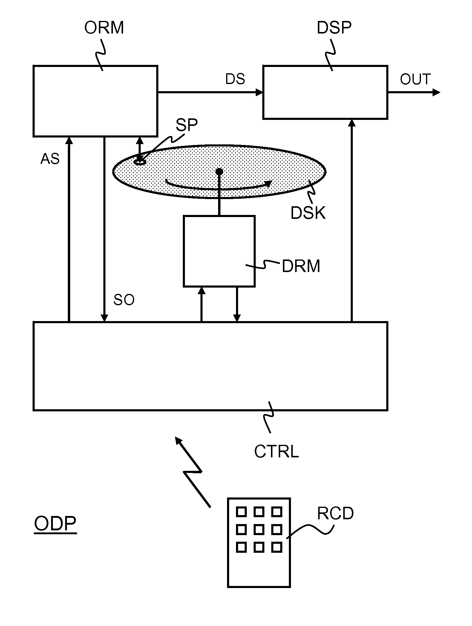
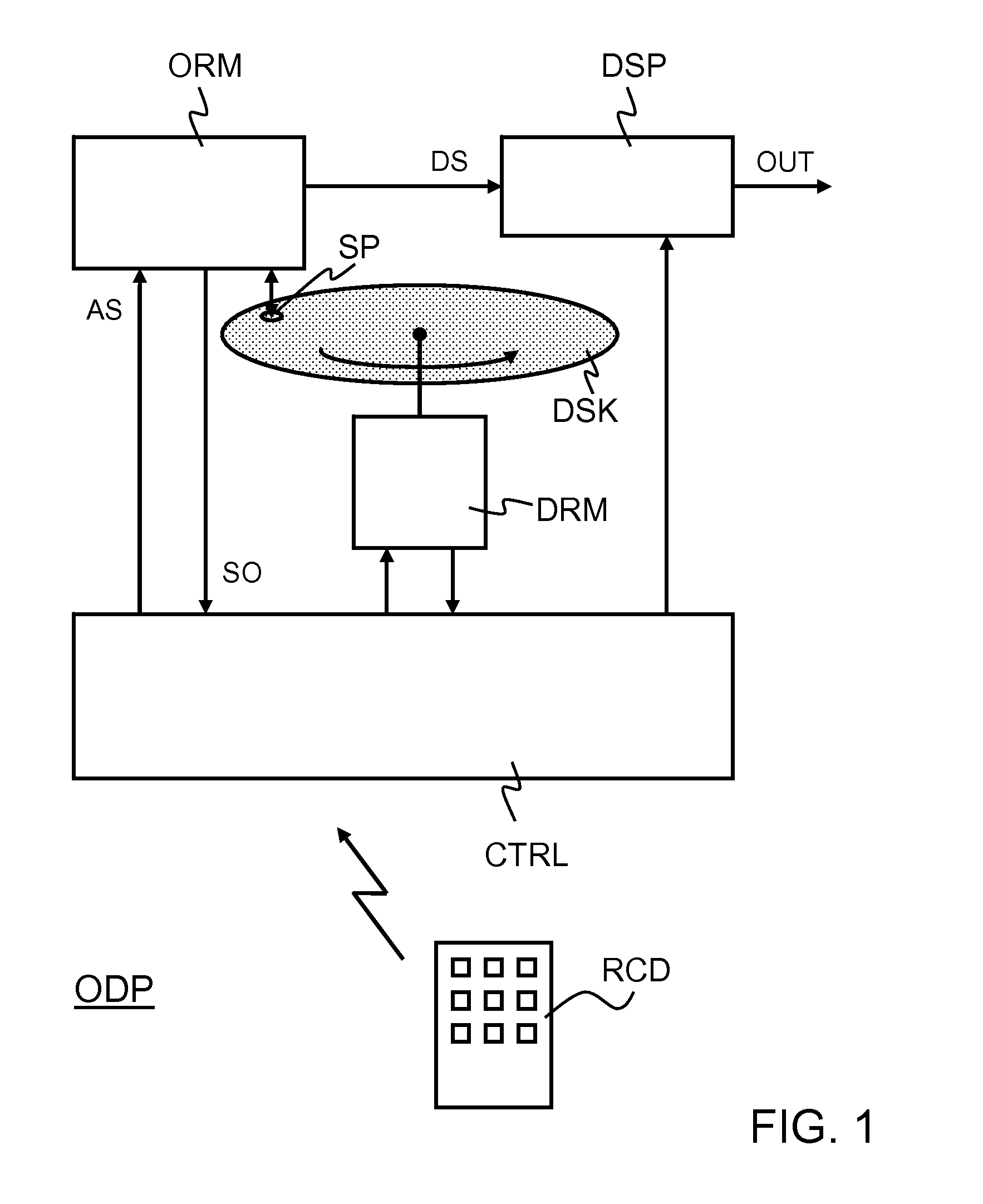
[0026]FIG. 1 illustrates an optical disk player ODP that is capable of reading an optical disk DSK, which comprises a relatively high density of data. The optical disk player ODP comprises an optical reader module ORM, a data signal processor DSP, a disk-rotation motor DRM, and a controller CTRL. The optical disk player ODP may further comprise a remote control device RCD. The controller CTRL may be in the form of, for example, a programmable processor that comprises a program memory. In that case, one or more software modules, which are stored in the program memory, define operations which the controller CTRL carries out.

[0027]The optical disk player ODP basically operates as follows. Let it be assumed that a user presses a play button on the remote control device RCD. The remote control device RCD sends a wireless signal to the controller CTRL. The controller CTRL interprets this wireless signal as a play command and, in response, causes the disk-rotation motor DRM to make the opt...


PUM

PropertyMeasurementUnit
wavelengthaaaaaaaaaa
near-field threshold value THNaaaaaaaaaa

Abstract

An optical storage interface apparatus comprises a lens module (LM). The lens module (LM) may comprise, for example, a solid immersion lens for near-field optical readout or near-field optical recording, or both. The lens module (LM) forms a light spot (SP) on an optical information carrier (DSK) in response to a light beam (BO) that is projected on the lens module (LM). A lens actuator (LA) moves the lens module (LM) from a rest position, which is relatively distant from the optical information carrier (DSK), to a read position, which is relatively close to the optical information carrier (DSK). A controller verifies whether the lens module (LM), when moving from the rest position to the read position, has a velocity that is below a velocity threshold or not. If not, the controller causes the lens actuator (LA) to pull back the lens module (LM) with respect to the optical information carrier (DSK).

Description

FIELD OF THE INVENTION[0001]An aspect of the invention relates to an optical storage interface apparatus.[0002]The optical storage interface apparatus may be, for example, a digital versatile disk (DVD) player, which can read data from a DVD disk, or a DVD recorder, which can also write data onto a DVD disk. The optical storage interface apparatus may comprise, for example, a near-field optical system, which allows high density data readout and storage. Other aspects of the invention relate to a method of controlling an optical storage interface, and a computer program product for an optical storage interface.BACKGROUND OF THE INVENTION[0003]The article entitled “High-Density Near-Field Optical Recording with a Solid Immersion Lens, Conventional Actuator, and a Robust Air Gap Servo” by Zijp F. et al., IEEE Transactions on Magnetics, Vol. 41, No. 2, February 2005, pages 1042-1046, describes a near-field optical recording system with a solid immersion lens in a conventional biaxial ac...

Claims


Application Information

Patent Timeline
Patent Type & Authority Applications(United States)
IPC IPC(8): G11B7/00
CPCG11B7/08511G11B7/1387G11B7/1201G11B7/121
Inventor LEE, JUIL
Owner KONINKLIJKE PHILIPS ELECTRONICS NV
Why Eureka
Try Eureka