Coherent Beam Combiner Based on Parametric Conversion

a beam combiner and parametric conversion technology, applied in laser details, instruments, optical devices, etc., can solve the problems of limiting the amount of external energy/power, large amount of heat generated in the optical cavity, and limiting the energy/power that can escape from the laser in the form of laser beams

Inactive Publication Date: 2009-07-16
GENERAL ATOMICS
View PDF17 Cites 7 Cited by
  • Summary
  • Abstract
  • Description
  • Claims
  • Application Information

AI Technical Summary

Problems solved by technology

A problem with this approach is that a large amount of heat is generated in the optical cavity as more particles in the gain medium are excited to higher energy states and light is amplified.
The large amount of heat generated in the gain medium and problems removing the heat, effectively limits the amount of external energy / power that can be practically introduced into the optical cavity and limits the energy / power that can escape from the laser in the form of a laser beam.
This leads to phase differences at the spatial combiner that must be compensated for.
This phase control aspect contributes significantly to the cost, complexity and feasibility of designing a high powered laser composed of multiple smaller laser beams.

Method used


Image

  • Coherent Beam Combiner Based on Parametric Conversion
  • Coherent Beam Combiner Based on Parametric Conversion
  • Coherent Beam Combiner Based on Parametric Conversion

Examples


Embodiment Construction

[0023]The following description is not to be taken in a limiting sense, but is made merely for the purpose of describing the general principles of exemplary embodiments. The scope of the invention should be determined with reference to the claims.

[0024]Reference throughout this specification to “one embodiment,”“an embodiment,” or similar language means that a particular feature, structure, or characteristic described in connection with the embodiment is included in at least one embodiment of the present invention. Thus, appearances of the phrases “in one embodiment,”“in an embodiment,” and similar language throughout this specification may, but do not necessarily, all refer to the same embodiment.

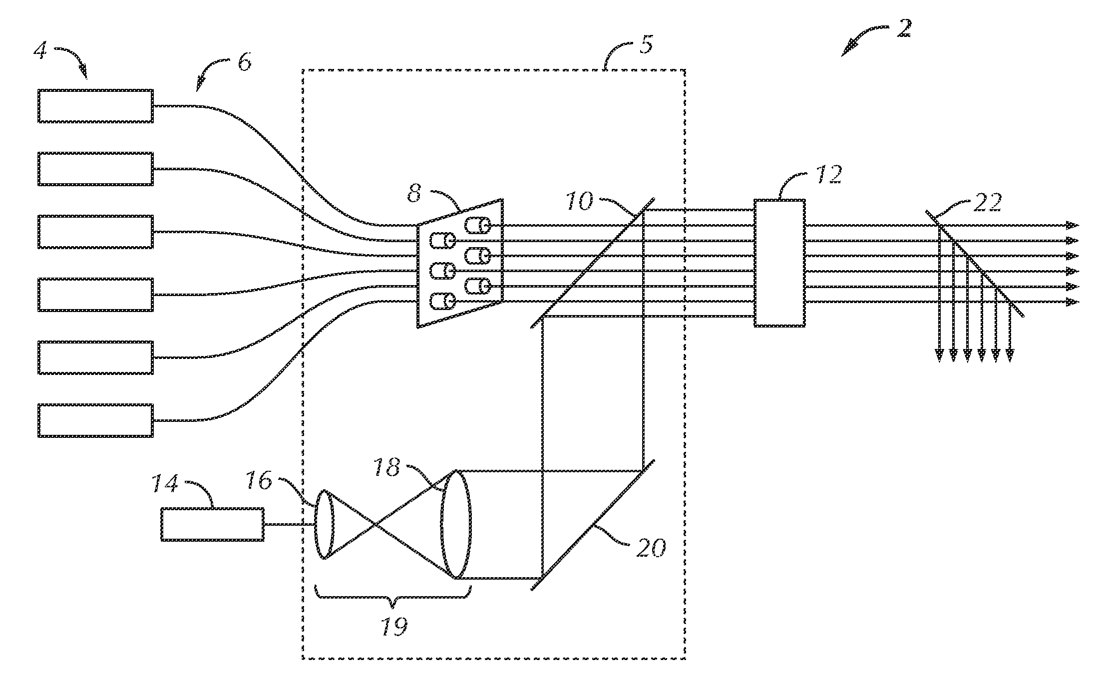
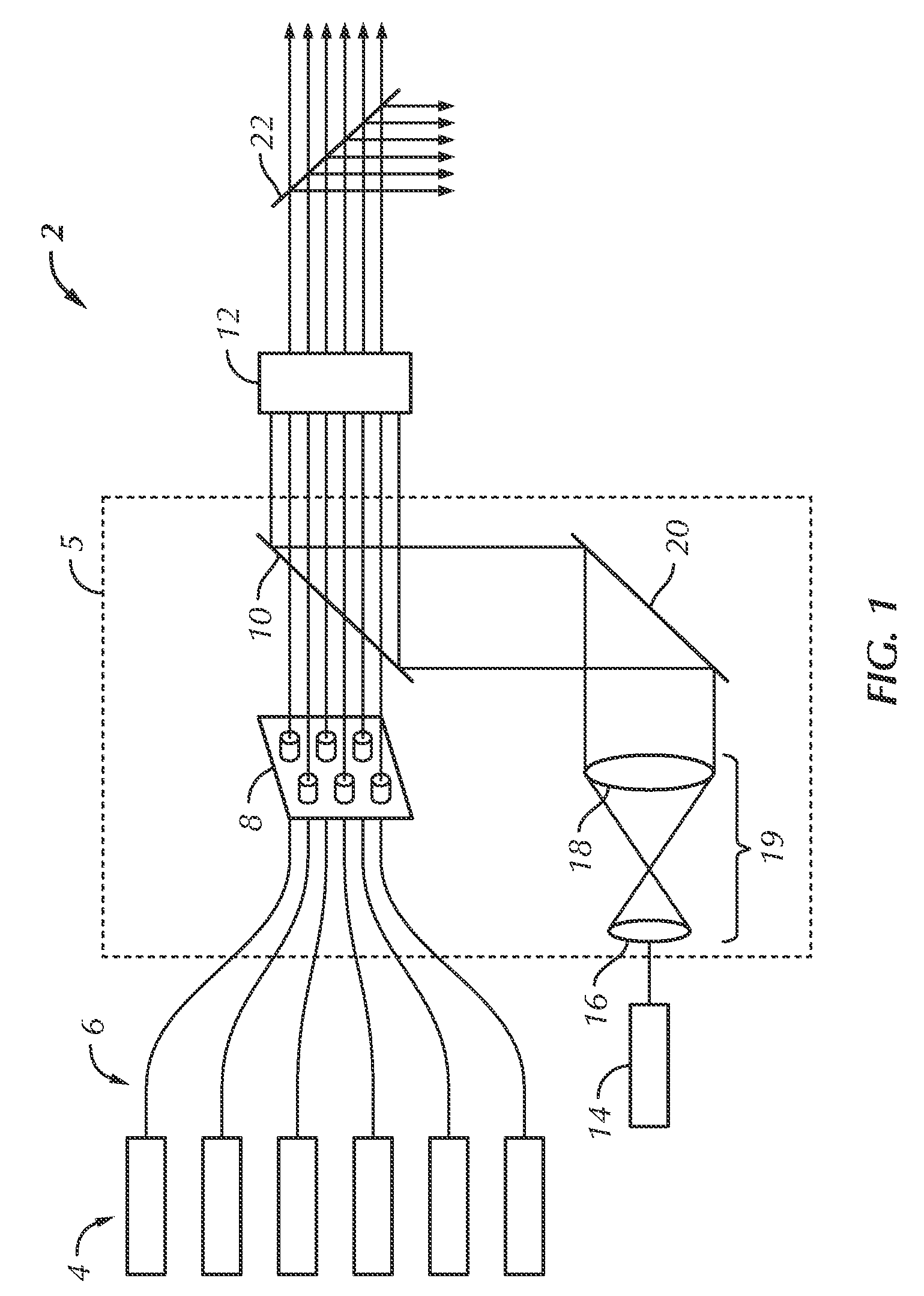
[0025]Referring first to FIG. 1, an embodiment of the invention is illustrated showing a beam combiner 2. The beam combiner 2 has a plurality of pumps 4. The plurality of pumps 4 are optically connected with an aperture array 8 through a plurality of waveguides 6 or optical beam directors....


PUM


Abstract

Methods and systems are provided to form a single coherent beam of light from a plurality of smaller beams of light. In one implementation a beam combiner comprising a beam director is configured to direct a seed beam of coherent light and a plurality of pump beams of coherent light; and a nonlinear converter is configured to combine the seed beam and the plurality of pump beams directed by the beam director to produce a substantially coherent wave front.

Description

BACKGROUND OF THE INVENTION[0001]1. Field of the Invention[0002]The present invention relates generally to a system and method for combining multiple light beams, and more specifically to a system and method for combining multiple coherent light beams having different phases.[0003]2. Discussion of the Related Art[0004]A laser includes a gain medium inside an optical cavity. The optical cavity typically has opposing mirrors with one of the mirrors being partially transparent. The gain medium is supplied with electrical or optical energy from an external source. The energy is absorbed by the gain medium exciting particles to higher energy states. Particles in low energy states absorb photons and particles in high energy states release photons. When enough energy is introduced, the number of high energy particles in the gain medium exceeds the number of low energy particles and more photons are released than are absorbed and light inside the gain medium is amplified. The released photo...

Claims


Application Information

Patent Timeline
Patent Type & Authority Applications(United States)
IPC IPC(8): H01S3/10
CPCH01S3/005G02F1/3534
Inventor SCHMIDT, BODO
Owner GENERAL ATOMICS
Why Eureka
Try Eureka