
Ship attitude motion component removal method based on spatial displacement

A technology of space displacement and ship movement, applied in the direction of radio wave reflection/re-radiation, using re-radiation, measuring devices, etc., can solve problems such as changes in the radar irradiation area, offset of the hull position, and influence on the accurate extraction of radial velocity

Active Publication Date: 2021-02-23
CHINA SHIP DEV & DESIGN CENT
View PDF3 Cites 0 Cited by
  • Summary
  • Abstract
  • Description
  • Claims
  • Application Information

AI Technical Summary

Problems solved by technology

However, when the ship is at a standstill, the radar placed on the deck cannot maintain a long-term stable state like the shore-based radar. This movement will shift the position of the hull and cause the attitude angle of the antenna to change continuously
In addition, for a ship sailing at high speed, although the forward motion plays a dominant role, the hull will still be subject to wave maneuvering from six degrees of freedom at all times, which will cause the ship's six degrees of freedom motion attitude angle and radar irradiation area to have no effect. change all the time
From the analysis results of the echo characteristics, it can be seen that the high-speed navigation of the hull and the six-degree-of-freedom motion and other attitude motion components will superimpose an additional velocity component that changes with time on the echo Doppler spectrum, which affects the accurate extraction of the radial velocity of the real water particle. , resulting in an increase in the error of wave parameter estimation

Method used


Image

  • Ship attitude motion component removal method based on spatial displacement
  • Ship attitude motion component removal method based on spatial displacement
  • Ship attitude motion component removal method based on spatial displacement

Examples


Embodiment Construction

[0064] The present invention will be further described below in conjunction with accompanying drawing:

[0065] Step 1, please refer to figure 1 , the Doppler frequency shift caused by the radial velocity of sea surface water particles measured by shipborne coherent radar in any sailing state is composed of many different components. The main source of this "synthetic" Doppler shift is mainly Bragg waves, but it also includes additional modulation components such as ocean surface currents, instantaneous motion of moving platforms, gravity waves, breaking waves, and shadow modulation. Specific principles such as figure 1 Shown:

[0066] Synthesized Doppler shift f of shipborne coherent radar measurements echo The expression of (r) is:

[0067] f echo (r)=±f B +f cr +f ship (r) (1)

[0068] Among them, the meanings represented by each frequency shift component are: f B is the frequency shift caused by the intrinsic Bragg waves of the ocean; f cr is the frequency shi...


PUM


Abstract

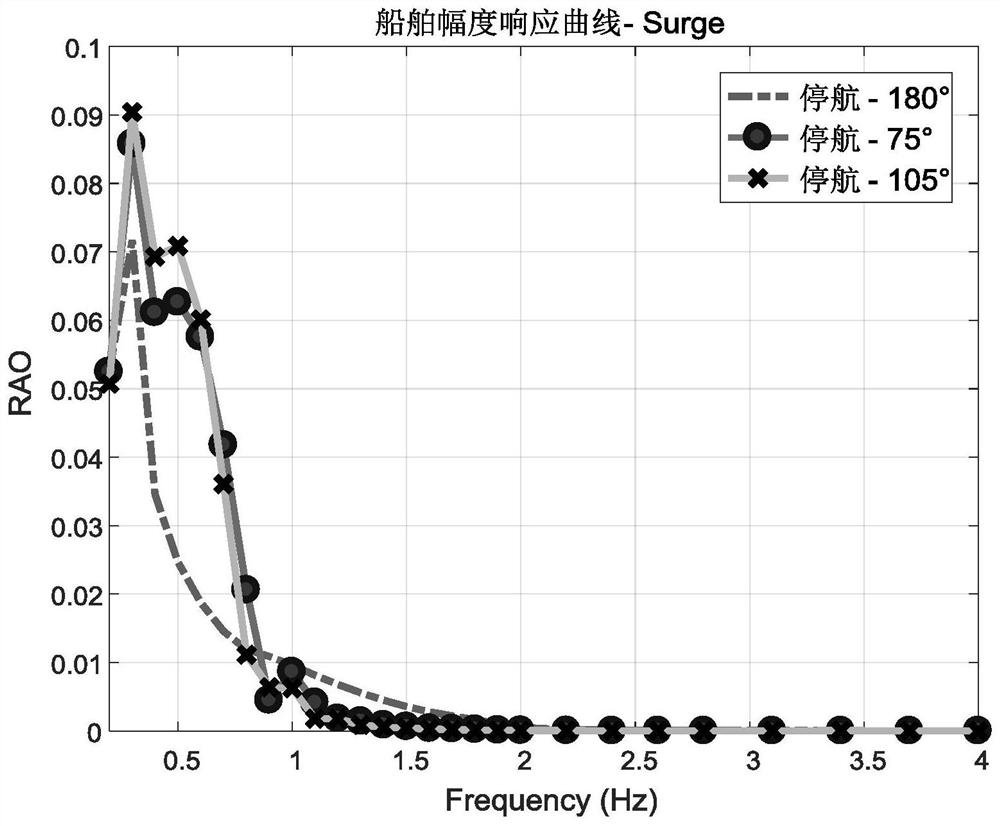
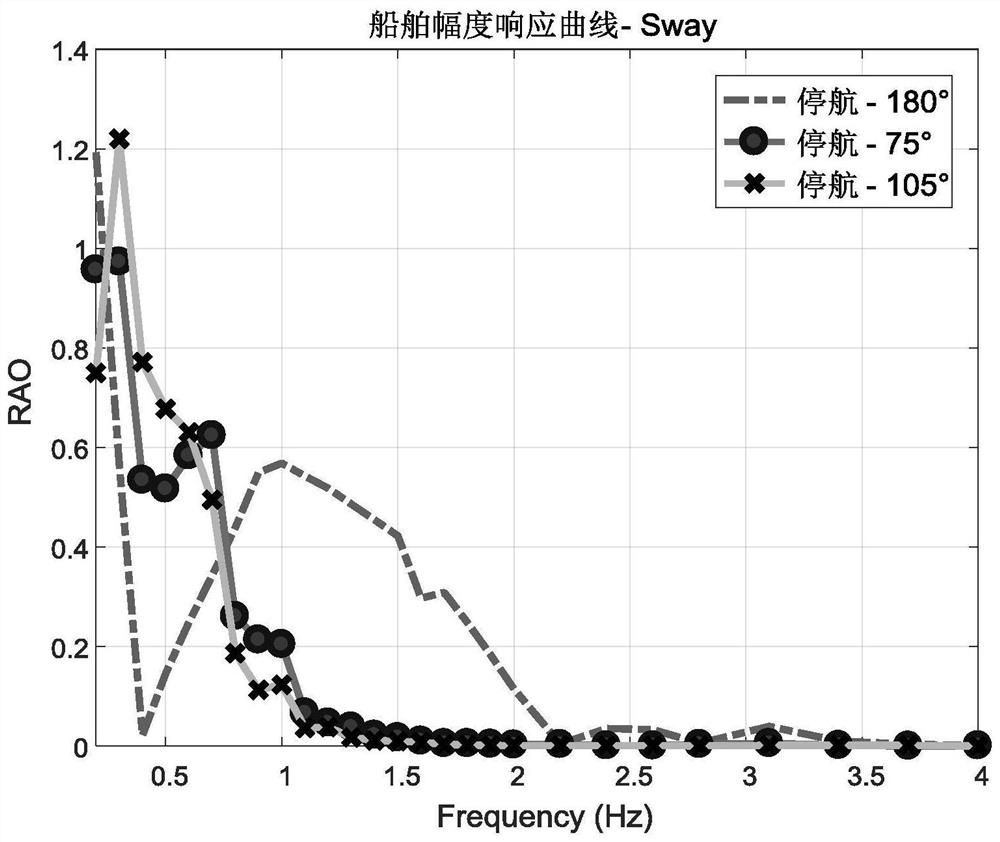
The invention discloses a ship attitude motion component removal method based on spatial displacement. The method comprises the following steps of: establishing an expression of comprehensive Dopplerfrequency shift measured by a shipborne coherent radar; calculating six-degree-of-freedom ship motion amplitude response factors on the basis of sea wave frequency component distribution characteristics according to the style data of a ship body under the condition that the ship body is excited by waves of a unit wave height; based on a sea wave frequency spectrum measured by the radar at the lastmoment, obtaining the fluctuation rule of a ship by constructing a wave surface equation of a regular sea surface, and then obtaining the sea surface wave height displacement of the position of the ship body; performing six-degree-of-freedom coordinate conversion under an earth coordinate system and a ship coordinate system; calculating the spatial displacement of a radar antenna in a time periodaccording to the space coordinate difference between a previous moment and a next moment; finally solving the additional Doppler frequency shift caused by the attitude motion component of the ship body, and removing the component from the radar echo Doppler frequency shift. The method can effectively improve the extraction effect of the radial velocity of real water quality points of sea waves, and improves the precision of coherent wave-measuring radar sea wave parameter inversion.

Description

technical field [0001] The invention belongs to the field of radar signal processing, and in particular relates to a method for removing motion components of a ship's attitude based on spatial displacement. Background technique [0002] my country has always been a large oceanic country, with a land coastline of more than 18,000 kilometers and a sea area under its jurisdiction of about 3 million square kilometers. Therefore, marine environment monitoring (including wave parameters, etc.) is of great significance in my country's marine economy, transportation and shipping, fish farming and other aspects. [0003] The shipborne coherent microwave radar is one of the many means of radio ocean remote sensing. This type of radar has the advantages of high measurement accuracy, less environmental interference, light and portable, etc. It can be installed on various types of ships, and can travel with the ship to near, far seas and various oceans to realize navigational observatio...

Claims


Application Information

Patent Timeline
IPC IPC(8): G01S7/36G01S7/40G01S13/88
CPCG01S7/36G01S7/4004G01S13/88
Inventor 陈曦谭辉陈亮邓林冀航
Owner CHINA SHIP DEV & DESIGN CENT
Learn More