Transmission apparatus and a reception apparatus in a multicarrier transmission system and a transmission method and a reception method using the multicarrier transmission system

a transmission system and multi-carrier technology, applied in the field of multi-carrier transmission systems, can solve problems such as phase fluctuations and deterioration of communication quality, and achieve the effect of reducing transmission efficiency and high-quality mobile communication

Active Publication Date: 2009-07-16
PANASONIC CORP
View PDF5 Cites 21 Cited by
  • Summary
  • Abstract
  • Description
  • Claims
  • Application Information

AI Technical Summary

Benefits of technology

[0054]According to the present invention, all of the subcarriers are respectively subjected to the modulation in an independent manner. Thus, without reducing the transmission efficiency, the inter-carrier interference caused by the frequency fluctuations, the amplitude fluctuations, phase fluctuations, or the like can be reduced, and high quality mobile communication can be realized.

Problems solved by technology

In addition, in a frequency conversion section of the transmission apparatus or the reception apparatus, phase fluctuations may be caused by phase noise in an oscillator circuit.
Therefore, in a case where the OFDM transmission system is used for the mobile communication, orthogonality among the subcarriers is impaired due to the above-mentioned frequency fluctuations, amplitude fluctuations, phase fluctuations, or the like, and inter-carrier interference among the subcarriers arises, leading to a problem of deterioration in communication quality.

Method used


Image

  • Transmission apparatus and a reception apparatus in a multicarrier transmission system and a transmission method and a reception method using the multicarrier transmission system
  • Transmission apparatus and a reception apparatus in a multicarrier transmission system and a transmission method and a reception method using the multicarrier transmission system
  • Transmission apparatus and a reception apparatus in a multicarrier transmission system and a transmission method and a reception method using the multicarrier transmission system

Examples


embodiment 1

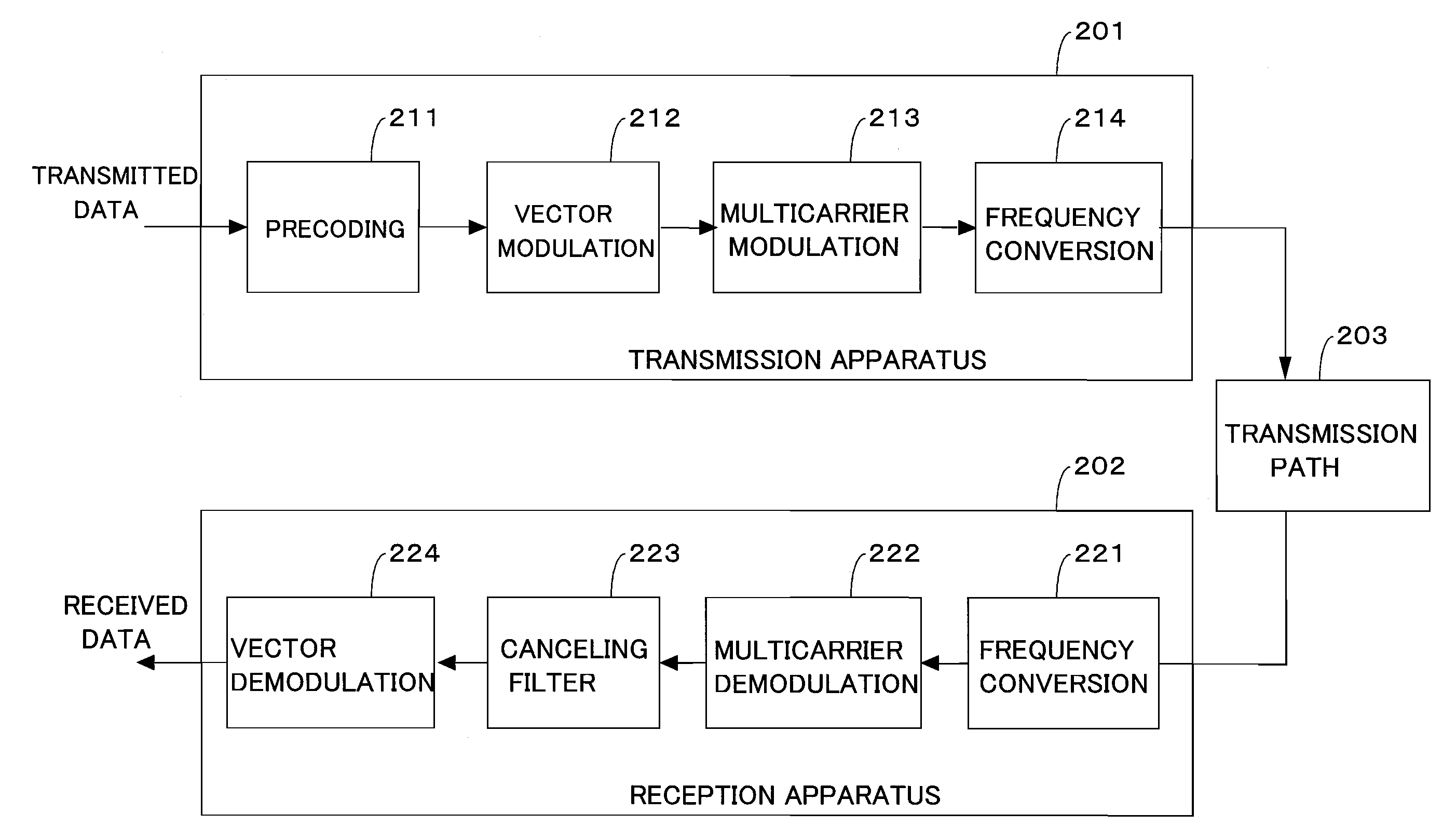
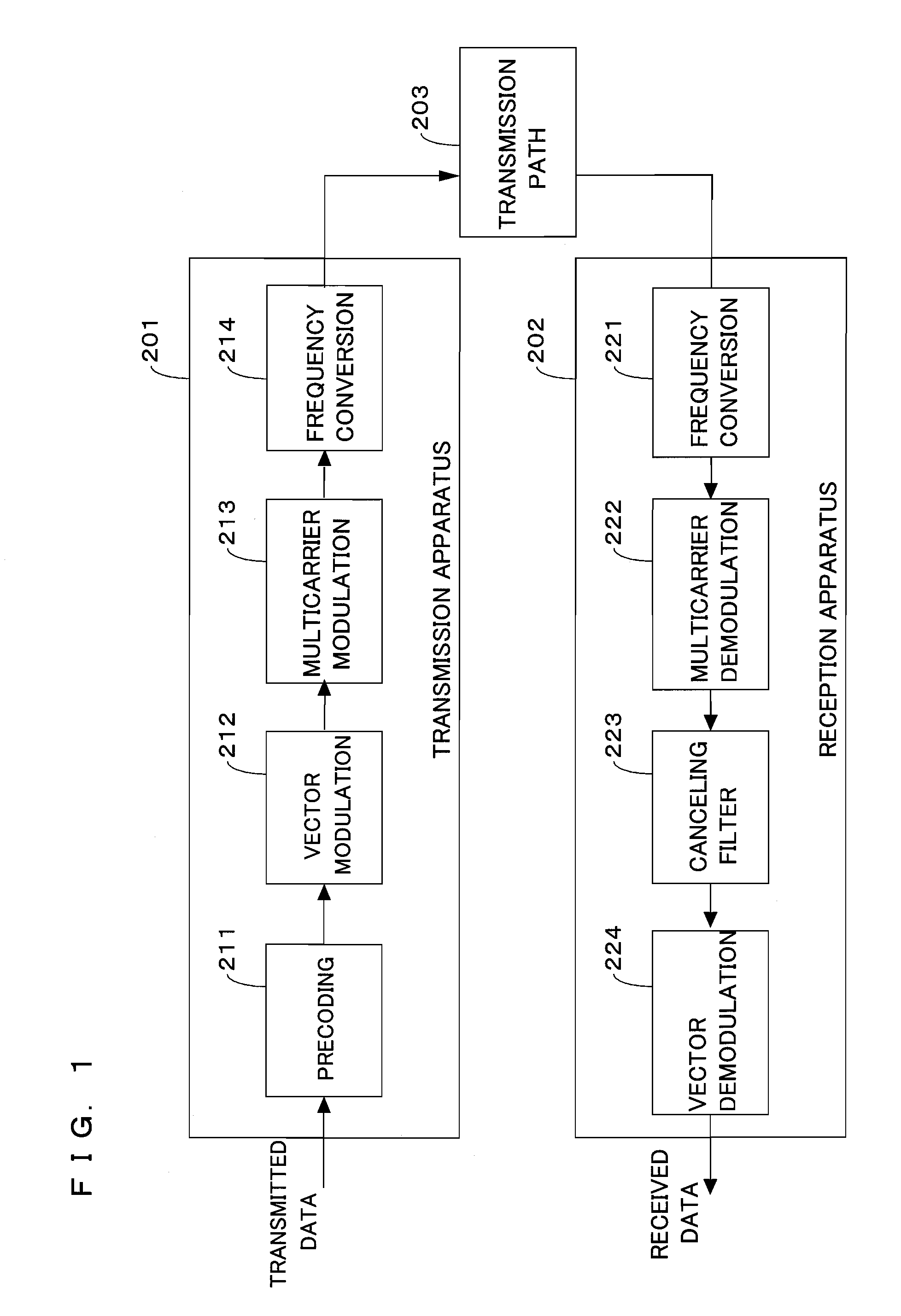
[0081]FIG. 1 is a block diagram illustrating a configuration of a transmission apparatus and a reception apparatus in a multicarrier transmission system according to an embodiment 1 of the present invention.

[0082]A transmission apparatus 201 receives transmitted data, performs multicarrier modulation based on the received transmitted data, and generate to output a multicarrier signal. The multicarrier signal outputted from the transmission apparatus 201 is given via a transmission path 203 to a reception apparatus 202. The reception apparatus 202 demodulates the multicarrier signal which has been received via the transmission path 203 and outputs received data.

[0083]The transmission apparatus 201 comprises a precoding section 211, a vector modulation section 212, a multicarrier modulation section 213, and a frequency conversion section 214. Hereinafter, operations of respective sections of the transmission apparatus 201 will be described. In order to describe the gist of the present...

example

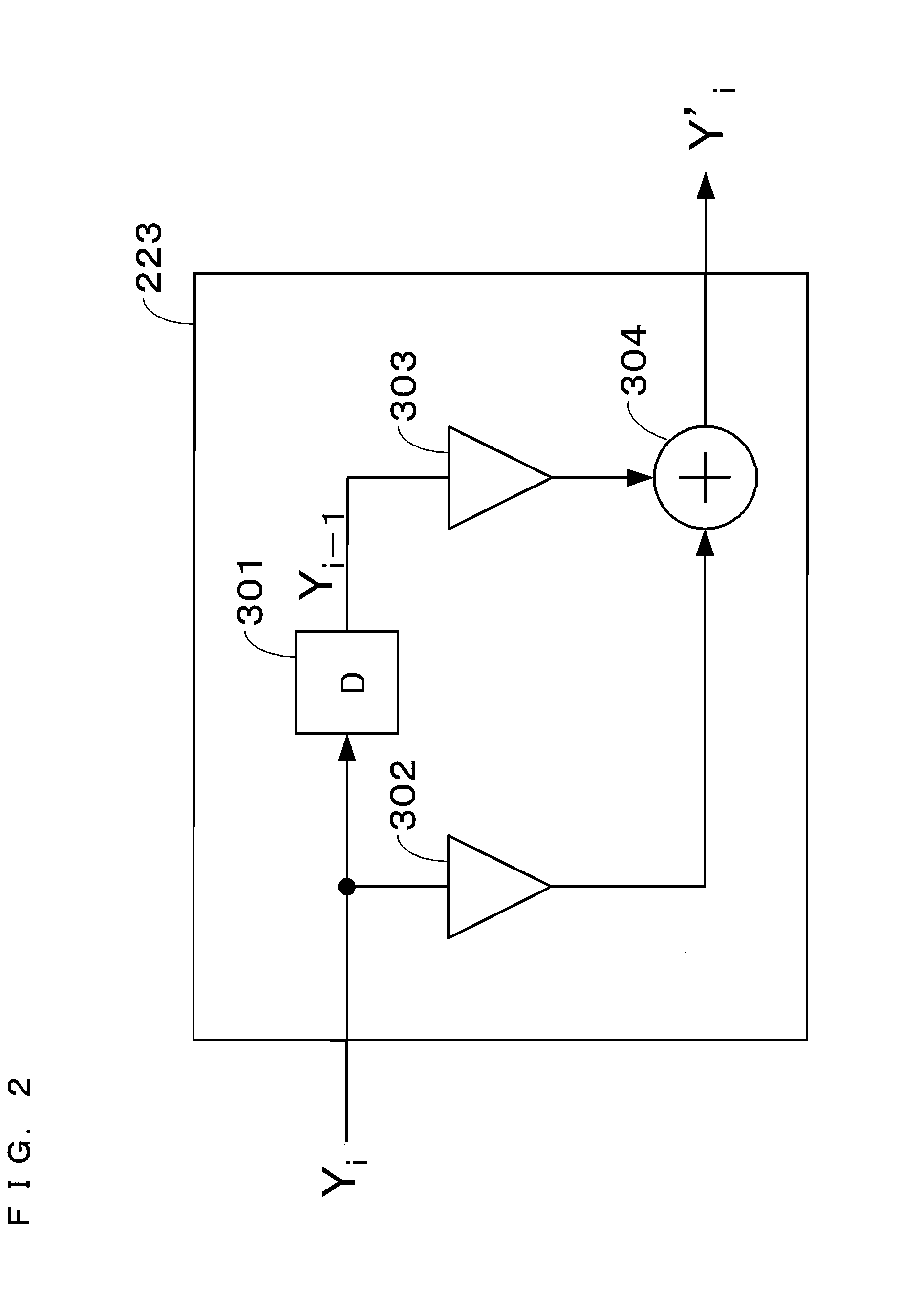
[0115]Hereinafter, an example of the embodiment 1 will be introduced. Effects of the precoding section 211 and the canceling filter section 223 will be described referring to FIGS. 2, 3, 4, and 7. FIG. 7 is a diagram showing calculation processing performed in the precoding section 211 and arithmetic processing performed in the canceling filter section 223. In this example, a case where a number of mapping points being M in the multicarrier modulation system is 4 is assumed. Although a specific modulation system is not particularly limited, for example, QAM can be used. A filter length of the canceling filter section 223 is 2 and a polynomial of a filter is P(D)=(1−D). FIG. 7 shows all combinations of calculations for obtaining the i-th modulation information X′i and the i-th modulation vector Y′i. In FIG. 7, Xi, X′i-1, X′i, Yi, Yi-1, Y′i are shown in respective columns in order starting from the leftmost column.

[0116]In FIG. 4, the transmitted data inputted to the precoding section...

embodiment 2

[0120]FIG. 8 is a block diagram illustrating a configuration of a reception apparatus in a multicarrier transmission system according to an embodiment 2 of the present invention.

[0121]As shown in FIG. 8, the reception apparatus 2020 includes a frequency conversion section 221, a multicarrier demodulation section 222, a canceling filter section 223, and a trellis decoding section 225. In the reception apparatus 2020, the vector demodulation section 224 in the reception apparatus 202 (see FIG. 1) according to the embodiment 1 is replaced by the trellis decoding section 225 and the other components can be the same as those in the embodiment 1. In the below description, the same reference numerals as those in the embodiment 1 are used to denote the same components in the present embodiment as those in the embodiment 1, and the description thereof will be omitted.

[0122]The trellis decoding section 225 receives N demodulation vectors, outputted by the canceling filter section 223, which h...


PUM


Abstract

An object is to reduce inter-carrier interference caused by frequency fluctuations, amplitude fluctuations, phase fluctuations, or the like without reducing a transmission efficiency. On a receiving end, a canceling filter section (223) is provided, alleviating the inter-carrier interference caused by the frequency fluctuations, the amplitude fluctuations, the phase fluctuations, or the like through filtering processing. On a transmitting end, a precoding section (211) is provided, facilitating determination of demodulation data in a vector demodulation section (224) on the receiving end through precoding processing. Or on the receiving end, a trellis decoding section (225) is provided, decoding the demodulation data through trellis decoding processing.

Description

TECHNICAL FIELD[0001]The present invention relates to a multicarrier transmission system, and more particularly, to a technique which reduces inter-carrier interference which is caused by fluctuations in a response of a transmission path in mobile communication and by phase noise or the like generated in a transmission apparatus and a reception apparatus.BACKGROUND ART[0002]As a method for performing stable communication in terrestrial digital television broadcasting, a wireless LAN (Local Area Network), etc. via a transmission path in which delay dispersion caused by a multipath is involved, a multicarrier transmission system which is typified by an orthogonal frequency division multiplexing (OFDM) transmission system (hereinafter, referred to as an OFDM transmission system) has been widely used. On the other hand, in mobile communication in which a transmission apparatus, a reception apparatus, or both of the transmission apparatus and the reception apparatus perform communication...

Claims


Application Information

Patent Timeline
Patent Type & Authority Applications(United States)
IPC IPC(8): H04L5/12H04B7/02
CPCH04L25/03343H04L27/2615H04L25/03821H04L2025/03414
Inventor KIMURA, TOMOHIROOMOTO, YUKIHIROMORI, KENICHI
Owner PANASONIC CORP
Why Eureka
Try Eureka