
Sealing structure for a bipolar plate of a fuel cell

Inactive Publication Date: 2009-07-16
YUAN ZE UNIV
View PDF2 Cites 5 Cited by
  • Summary
  • Abstract
  • Description
  • Claims
  • Application Information

AI Technical Summary

Benefits of technology

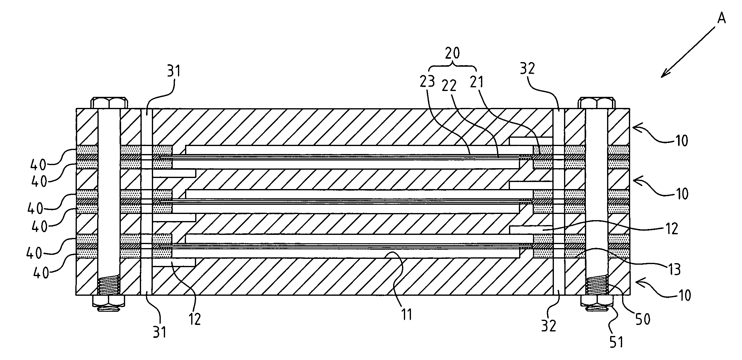
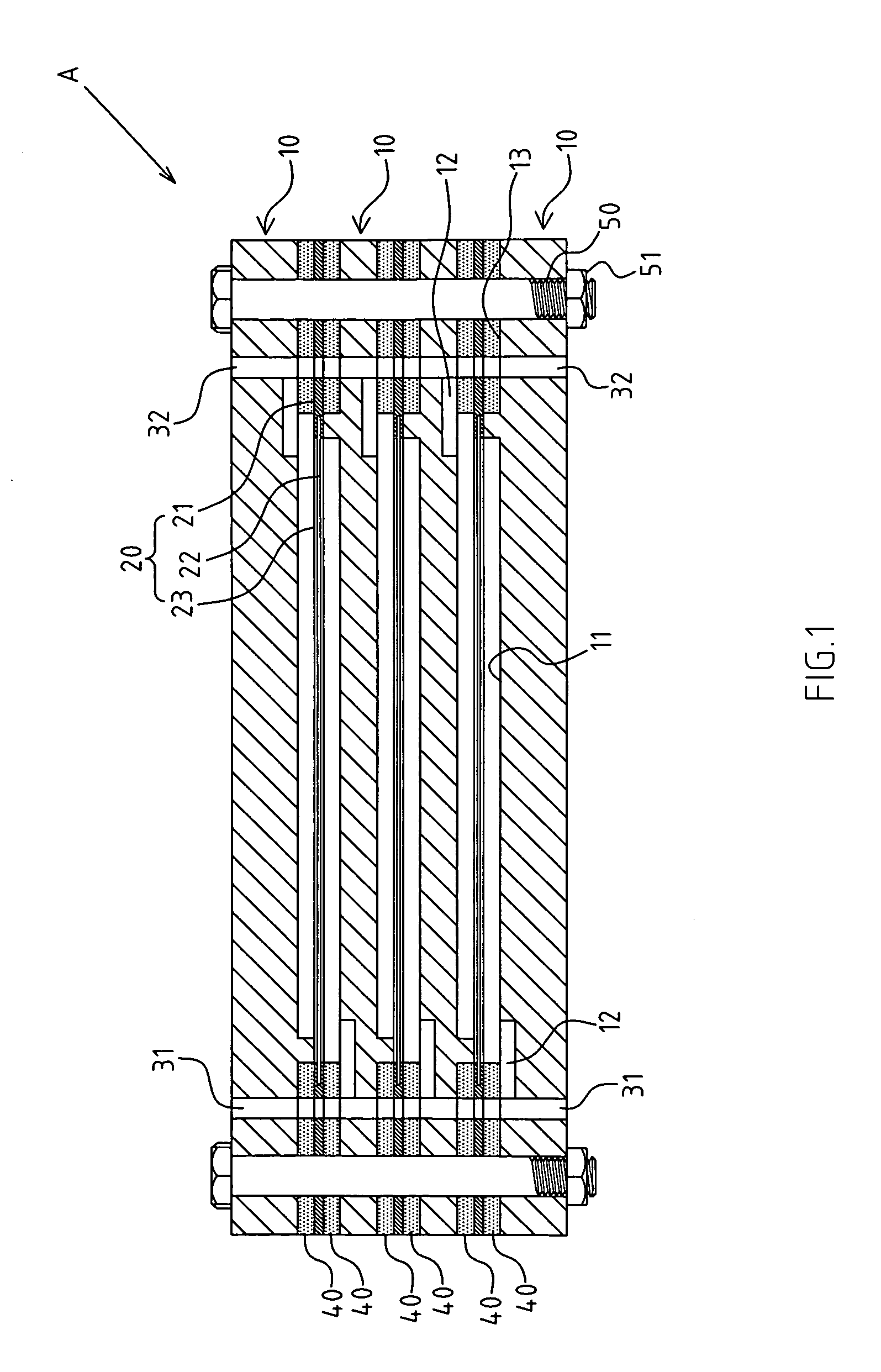
[0014]Based on the unique concave surface, when the bipolar plate, gas guidance and reaction layer and gasket of the fuel cell are fastened, the deformation amount of the gasket is accurately controlled through the height limitation of the concave surface. The air-tightness effect of the gasket is optimized, and the service life is greatly prolonged. Meanwhile, with the mating of concave surface, the locating state of the gasket is more stable for improved applicability.

Problems solved by technology

However, the bipolar plate is solidly coupled to the gas diffusion layer, so the coupling surface must be processed precisely to ensure the intended air-tightness, leading to much higher processing costs, greater risk for defects, and poorer economic efficiency.
Even if the coupling surface reaches the intended precision, the local stress generated by the pressure points of fittings (e.g. bolts and rivets) may lead to warping and deformation of the coupling surface when a plurality of bipolar plates and gas diffusion layers are overlapped and fastened.
As mentioned above, when the coupling surface generates a clearance, the gases of different properties will be mixed before reaching the gas diffusion layer, possibly leading to a negative influence on the generating efficiency of fuel cells or even an explosion hazard due to the contact reaction of excess fuels with different properties.
But, owing to the lack of measures for accurately controlling the pressure state of the gasket, the gasket will be prone to quick degradation and hardening, resulting in a shorter service life.

Method used


Image

  • Sealing structure for a bipolar plate of a fuel cell
  • Sealing structure for a bipolar plate of a fuel cell
  • Sealing structure for a bipolar plate of a fuel cell

Examples


Embodiment Construction

[0021]The features and the advantages of the present invention will be more readily understood upon a thoughtful deliberation of the following detailed description of a preferred embodiment of the present invention with reference to the accompanying drawings.

[0022]FIGS. 1-4 depict preferred embodiments of the bipolar plate's sealing structure of a fuel cell of the present invention. The embodiments are only provided for explanatory purposes with respect to the patent claims.

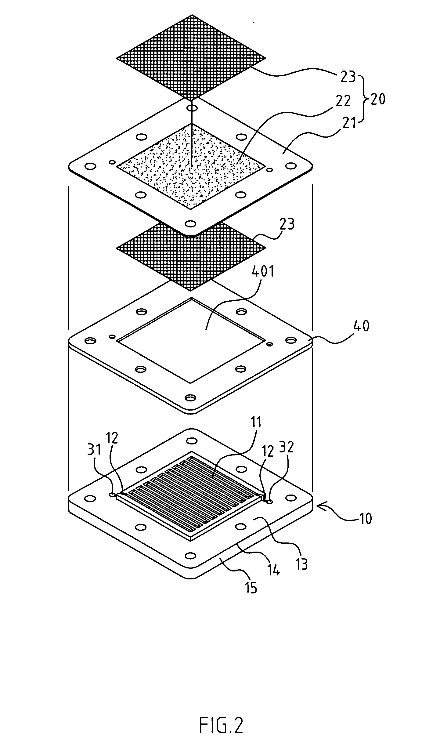
[0023]The fuel cell A comprises a plurality of bipolar plates 10, and a gas guidance and reaction layer 20 overlapped with the bipolar plates 10. Gas channel 11 is placed laterally onto the bipolar plates 10 corresponding to the gas guidance and reaction layer 20. The gas channel 11 has a serpentine pattern.

[0024]The first main gas channel 31 and second main gas channel 32 are arranged on the bipolar plates 10 at a distance from the gas channel 11. Different reacting gases, such as hydrogen and oxygen, are guided...


PUM


Abstract

The present invention provides a sealing structure for a bipolar plate of a fuel cell. The sealing structure includes a plurality of bipolar plates and a gas guidance and reaction layer. A gas channel is placed laterally onto the bipolar plate corresponding to the gas guidance and reaction layer. A gasket is located between a bipolar plate and the gas guidance and reaction layer. A permeable portion is formed on the gasket corresponding to the gas channel. A concave surface is placed laterally on the bipolar plate corresponding to the gas guidance and reaction layer for mating with the gasket. When the bipolar plate, gas guidance and reaction layer and gasket are fastened, the deformation amount of the gasket is accurately controlled through the height limitation of the concave surface.

Description

CROSS-REFERENCE TO RELATED U.S. APPLICATIONS[0001]Not applicable.STATEMENT REGARDING FEDERALLY SPONSORED RESEARCH OR DEVELOPMENT[0002]Not applicable.NAMES OF PARTIES TO A JOINT RESEARCH AGREEMENT[0003]Not applicable.REFERENCE TO AN APPENDIX SUBMITTED ON COMPACT DISC[0004]Not applicable.BACKGROUND OF THE INVENTION[0005]1. Field of the Invention[0006]The present invention relates generally to a fuel cell, and more particularly to an innovative fuel cell with a sealing structure for the coupling portion of the bipolar plate.[0007]2. Description of Related Art[0008]Including Information Disclosed Under 37 CFR 1.97 and 37 CFR 1.98.[0009]As far as a common fuel cell is concerned, the bipolar plate is a structure arranged at both sides of the membrane electrode assembly (MEA). The bipolar plate is made of materials featuring high conductibility and workability, such as graphite, aluminum and stainless steel. The coupling surface of the bipolar plate is provided with a flow channel for guid...

Claims


Application Information

Patent Timeline
IPC IPC(8): H01M8/02
CPCH01M8/0273Y02E60/50H01M2008/1095H01M8/242
Inventor WENG, FANG BORAY, SUHSU, CHUN-YINGLEE, CHIH-HUNG
Owner YUAN ZE UNIV
Learn More