Method and apparatus for network managed radio frequency coverage and mobile distribution analysis using mobile location information

US20090181664A1Inactive Publication Date: 2009-07-16LUCENT TECH INC +1

Image

  • Method and apparatus for network managed radio frequency coverage and mobile distribution analysis using mobile location information
  • Method and apparatus for network managed radio frequency coverage and mobile distribution analysis using mobile location information
  • Method and apparatus for network managed radio frequency coverage and mobile distribution analysis using mobile location information

Examples


Embodiment Construction

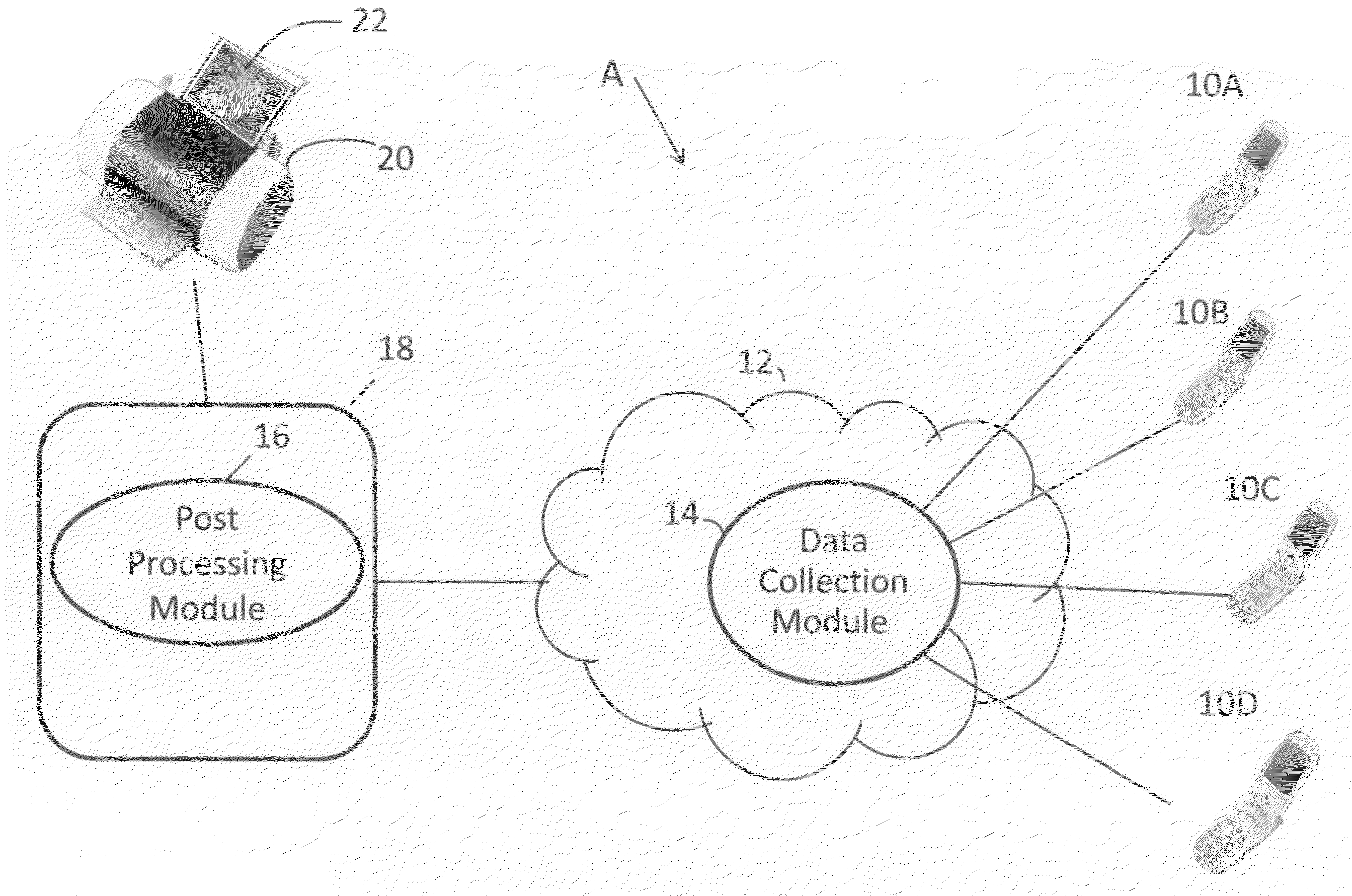
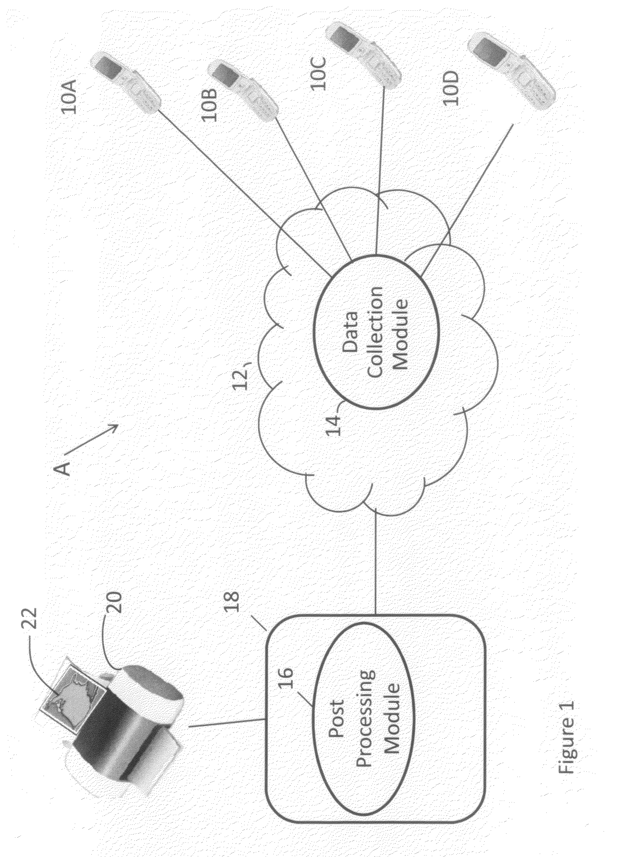
[0032]Referring now to the drawings wherein the showings are for purposes of illustrating the disclosed embodiments only and not for purposes of limiting the claimed subject matter, FIG. 1 provides an overall view of a system into which the presently described embodiments may be incorporated. The communications infrastructure A is shown. The communications infrastructure A includes a plurality of mobile units, 10A, 10B, 10C, 10D, a network provider 12, and a data collection module 14. The communications infrastructure A also includes a post processing network element 18, a post processing module 16, a coverage map printer 20 and a coverage map 22. It should be understood that this represents but one embodiment of the communications network infrastructure. The present disclosure could be incorporated in a variety of communication network configurations.

[0033]In operation, as described in greater detail below, the presently described embodiments are directed towards a method for ident...


PUM


Abstract

A system and method for identifying geographical areas which distribute poor radio frequency coverage is provided. The method includes measuring a radio frequency signal of a mobile unit in response to a trigger. The method continues with mapping the location data of the radio frequency signal which represents the positioning of the mobile unit at a given time. The method continues with recording the location data of the mobile unit and storing the location data in a database. The trigger, which prompts the radio frequency measurement, may be a timer expiring, a dropped call, or a mobile power increase signaling a weak signal. In any form, a post processing module may be configured in order to record, store and organize the location data into a report, such as a coverage map. Embodiments of this disclosure will display geographic areas that have poor radio frequency and allow for an administrator to identify trouble spots by a geographical region.

Description

BACKGROUND OF THE DISCLOSURE[0001]This disclosure relates to a method for identifying areas that have poor signal strength coverage within a cell. More particularly, this disclosure relates to measuring radio frequency signals in response to a trigger where the signals identify the signal strength in the given cell area.[0002]While this disclosure is particularly directed towards measuring signal strength in problem areas and will thus be described with particular reference thereto, it will be appreciated that this disclosure may have usefulness in other fields and applications. For example, this disclosure may be useful in a variety of telecommunication services where it is helpful to determine the strength of a Radio Frequency (RF) signal, including hot spots and dead spots.[0003]By way of background, in order for a wireless network to function correctly, there needs to be continuous RF coverage. Inadequate RF coverage results in dropped calls and poor voice quality. Because servi...

Claims


Application Information

Patent Timeline
16 Jul 2009
Publication
US20090181664A1
IPC
H04M3/22
CPC
H04W16/22; H04W64/00; H04W24/10
Inventors
KURUVILLA, EAPEN; BETRENCOURT, SAMUEL