Reception Boosting Accessory

a technology of accessories and antennas, applied in the direction of substation equipment, antenna details, antennas, etc., can solve the problems of affecting the reception of the device's antenna, affecting and exacerbate the reception problems encountered, so as to improve boost the reception of the device.

Inactive Publication Date: 2009-07-16
VINCI BRANDS LLC
View PDF6 Cites 75 Cited by
  • Summary
  • Abstract
  • Description
  • Claims
  • Application Information

AI Technical Summary

Benefits of technology

[0008]An embodiment of the present invention is directed toward a carrying case for use with a portable electronic device. The carrying case includes a conductive material such as copper foil that functions as a coupling element. The coupling element is positioned in the case such that it is adjacent an antenna of the device when the device is held in the carrying case. The coupling element capacitively or inductively couples to the device antenna and improves the reception of the device. The coupling element is preferably shaped to correspond to a profile of the antenna in the device. A case antenna is electrically connected to the coupling element. The case antenna can be internal or extendable and adjustable. A signal booster may be included in the case to amplify the signal received by the case antenna. The amplified signal is then coupled to the device antenna by the coupling element thereby boosting the device's reception. A rechargeable battery powers the signal booster. Alternatively, the signal booster can be powered from the device power supply in a parasitic manner.
[0009]Another embodiment of the present invention is directed toward an accessory for an electronic device. The accessory is configured as a replacement panel for a housing of the device. The replacement panel includes a signal boosting element positioned in the panel. The signal boosting element is positioned in the replacement panel such that, when the replacement panel is installed on the device, the signal boosting element is adjacent an antenna of the electronic device. The signal boosting element couples to the device's antenna thereby improving the reception of the device.
[0010]Yet another embodiment of the present invention is directed toward a case for an electronic device. The case includes a front panel and back panel that connect to substantially enclose the electronic device. A repositionable coupling element is positioned on one of the panels such that it is held adjacent an internal antenna of the device. The coupling element, the exterior of the device and the internal antenna of the device form a capacitor that increases the reception capability of the device. An antenna and amplifier are electrically connected to the coupling element. The coupling element couples the amplified signal received from the amplifier to the antenna of the device when the device is held in the case. A shielding portion prevents unwanted signals from the device from coupling to the coupling element.

Problems solved by technology

Unfortunately, a better antenna is typically a larger antenna.
However, a limited number of individuals located on the fringes of the device's reception range would strongly prefer better reception.
While a device can be retrofitted with a more capable antenna, it is difficult to do so in a suitable, ascetic and economical matter.
Unfortunately, these cases may impede the reception of the device's antenna when the device is positioned within the case.
This can further exacerbate the reception problems encountered in some locations.
Many cases also suffer from the draw back that the device's outputs, display and controls are not easily accessible through the case's exterior.

Method used


Image

  • Reception Boosting Accessory
  • Reception Boosting Accessory
  • Reception Boosting Accessory

Examples


Embodiment Construction

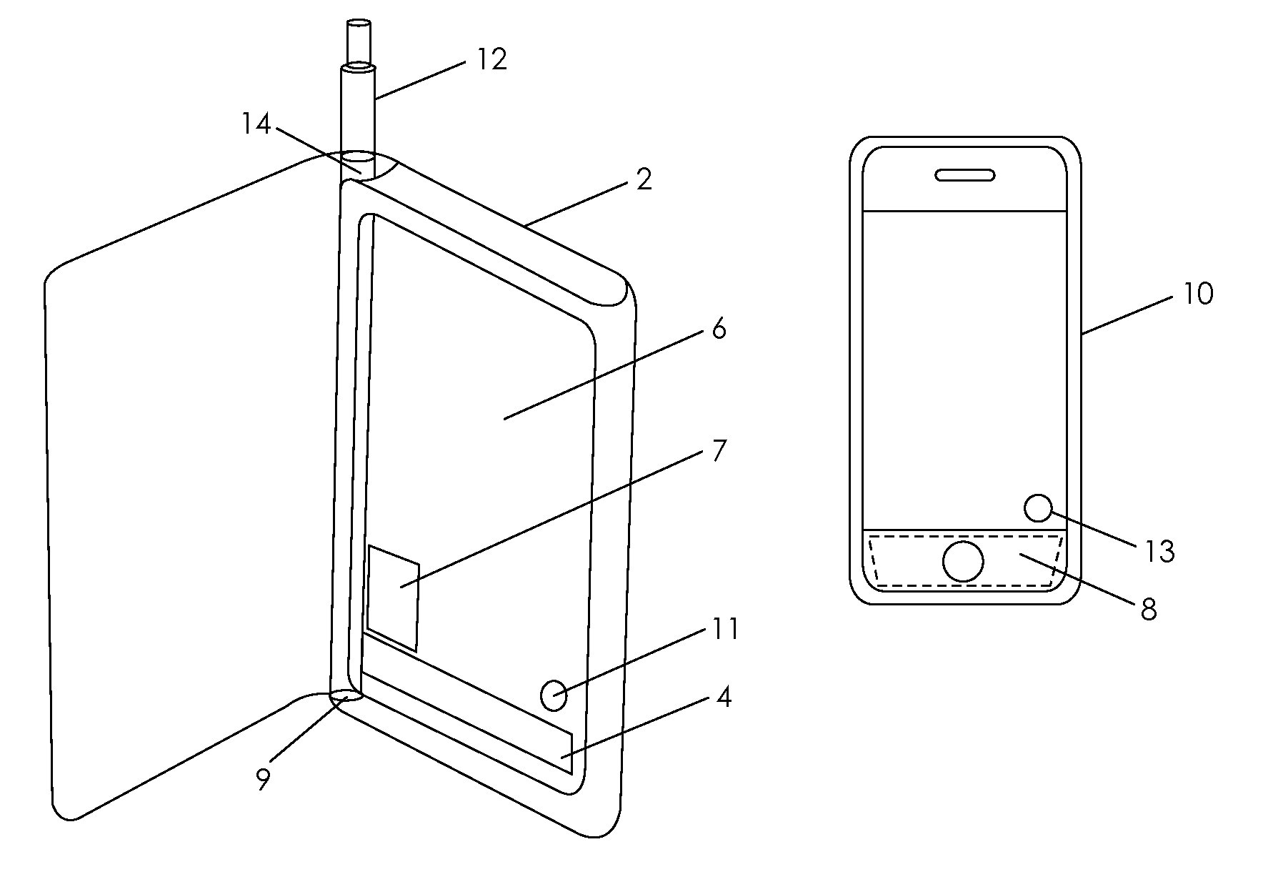
[0016]Referring now to FIG. 1, an illustration of a device case 2 constructed in accordance with an embodiment of the present invention is shown. The case 2 has a capacitively coupling element 4, constructed from a conductive material such as copper foil, positioned on an inner face 6 of the case. The coupling element 4 is preferably positioned adjacent an internal antenna 8 of an electronic device 10 when the device is enclosed within the case 2. The capacitively coupling element 4 and the device's internal antenna 8 form the plates of a capacitor and couple to the internal antenna 8 of the electronic device 10 to the element 4 of the device 10. A shielding portion 7, also constructed from a conductive foil, can be constructed to minimize any undesirable coupling to the coupling element 4 from electronics other than the antenna 8 in the device 10. The coupling element 4 can be electrically connected to an extendable antenna 12 that can be retracted into the spine 14 of the case 2 f...


PUM


Abstract

A carrying case for a portable electronic device includes a coupling element that couples to an antenna of the device without establishing a direct electrical connection. The coupling element increases the reception of the device by increasing the effective size of the antenna. The coupling element is designed to correspond to the reception capabilities of the device for which the case is designed. Preferably, the coupling element is a copper foil that is positioned in the case such that it is adjacent the antenna of the device when the device is held within the case. The copper foil is shaped to correspond to a profile of the device. An antenna and signal amplifier can be used in connection with the coupling element to further boost the device's reception capability.

Description

CROSS-REFERENCES TO RELATED APPLICATIONS[0001]The present application claims priority from co-pending Provisional Patent Application No. 61 / 018,661 entitled “Reception Boosting Accessory” filed Jan. 2, 2008.STATEMENT REGARDING FEDERALLY SPONSORED RESEARCH OR DEVELOPMENT[0002]Not ApplicableREFERENCE TO SEQUENCE LISTING OR COMPUTER PROGRAM LISTING APPENDIX[0003]Not ApplicableFIELD OF THE INVENTION[0004]The present invention is directed toward an accessory for use with an electronic device that electromagnetically couples a signal booster in the case to an antenna of the device to improve the reception of the antenna.BACKGROUND OF THE INVENTION[0005]A wide variety of electronic devices utilize antennas to receive or send electromagnetic signals. Unfortunately, a better antenna is typically a larger antenna. On small portable devices in particular, a compromise has to be made between reception capability and size and weight restrictions. Often, a small antenna will function perfectly we...

Claims


Application Information

Patent Timeline
Patent Type & Authority Applications(United States)
IPC IPC(8): H04M1/00
CPCH01Q1/243H01Q25/00H01Q1/244
Inventor GRIFFIN, JR., PAUL P.REYNOLDS, DAVID M.
Owner VINCI BRANDS LLC
Why Eureka
Try Eureka