Apparatus and method for generating cavitational features in a fluid medium

a technology of cavitation and fluid medium, which is applied in the direction of liquid chemical processes, gas-gas reaction processes, liquid-gas reactions of thin-film type, etc., can solve the problems of large amount of energy, large amount of heavy equipment and a lot of foundation space, and reduce the yield of biodiesel, so as to reduce the fluid pressure, and reduce the fluid pressure

Inactive Publication Date: 2009-07-16
CAVITATION TECH
View PDF17 Cites 18 Cited by
  • Summary
  • Abstract
  • Description
  • Claims
  • Application Information

AI Technical Summary

Benefits of technology

[0018]In a first preferred embodiment, the fluidic medium is flowed through sequential compartments of progressively smaller diameter. The progressively smaller diameters decrease the fluid pressure and generate cavitational fluid features in the fluidic medium. The fluidic medium may then be forced to flow around a conical cap positioned in the passageway such that the fluidic medium flows through a narrow circumferential opening. Flowing through this narrow circumferential opening further decreases the fluid pressure and generates additional cavitational fluid features in the fluidic medium. In addition, the fluidic medium may be forced to flow through orifices in a constrictor plate positioned in the passageway such that the fluidic medium flows through multiple narrow orifices. Flowing through these multiple narrow orifices further reduces the fluid pressure and generates even more cavitational fluid features in the fluidic medium.
[0019]In a second preferred embodiment, the fluidic medium is passed through an inlet orifice having a diameter much smaller than the diameter of the passageway. As with the orifices above, the fluid pressure is reduced and cavitational fluid features are generated in the fluidic medium. The fluidic medium is then passed through a first transition compartment having a first set of inner surface features. These inner surface features generate even more cavitational fluid features. The fluidic medium is then flowed i...

Problems solved by technology

In such high pressure systems, the temperature of the oils and fats exceeds 50° C. Such a process requires large amounts of energy input, heavy equipment and a lot of foundation space.
High FFA content, in combination with conventional base-catalyzed transesterification, lowers the yield of biodiesel and produces by-products like soap stock and glycerin.
Such a device requires large amounts of energy and also produces a very high outlet pressure, u...

Method used


Image

  • Apparatus and method for generating cavitational features in a fluid medium
  • Apparatus and method for generating cavitational features in a fluid medium
  • Apparatus and method for generating cavitational features in a fluid medium

Examples


Embodiment Construction

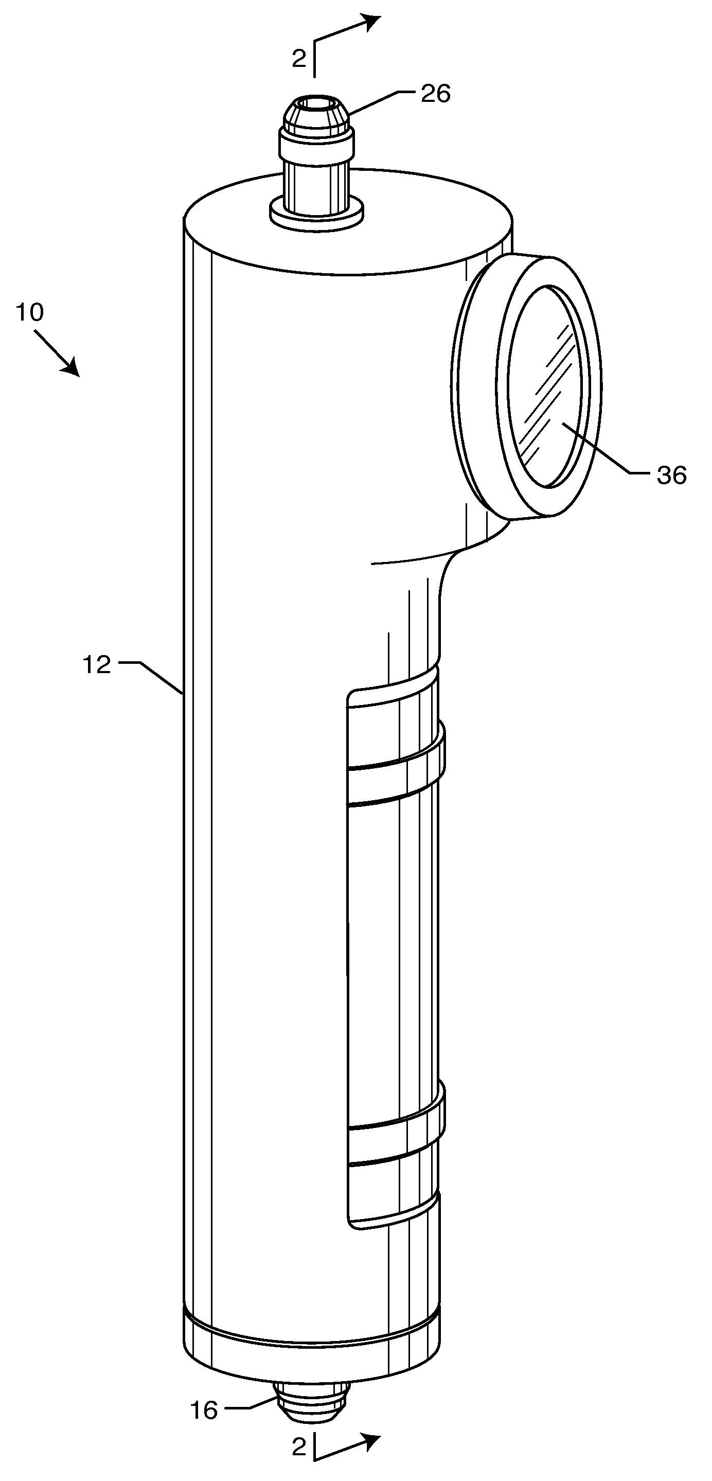
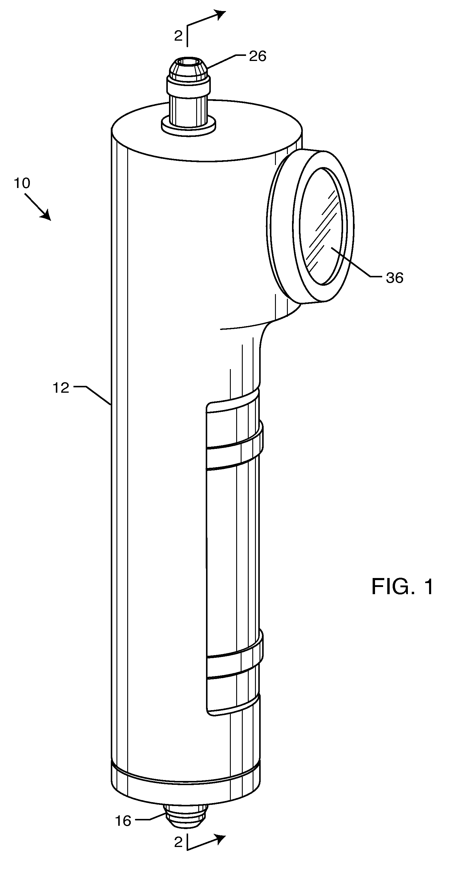
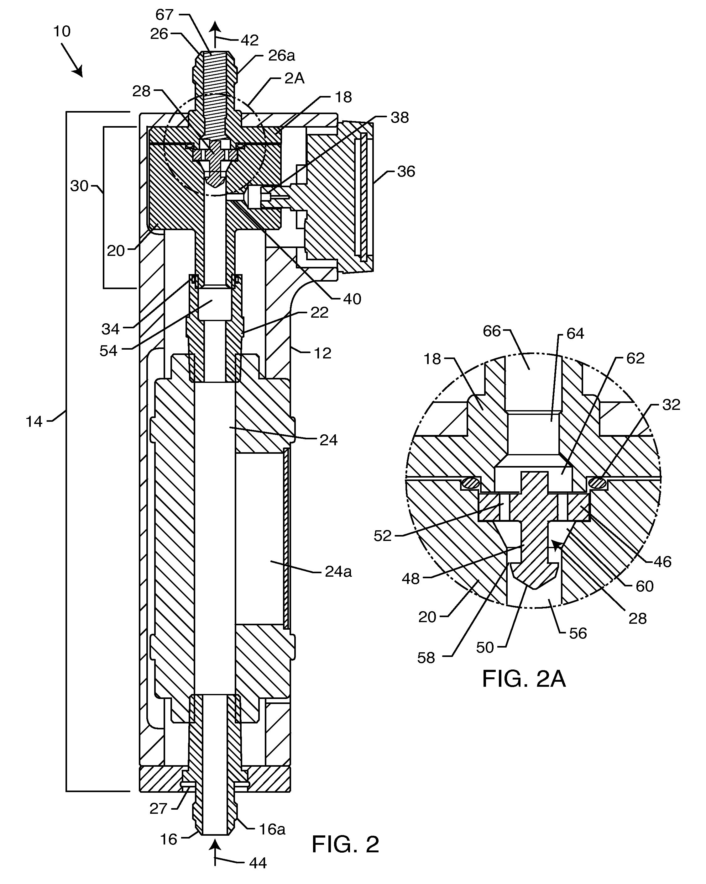
[0042]The present invention is directed to an apparatus and method for processing a liquid via a hydrodynamic cavitation process with the result being the creation of long-term stable and ultra-thin emulsions and dispersions. The cavitation process described herein is a mixing process at the molecular level within the described nano-cavitation generator. All components inside the apparatus are influenced by pressure impulses and advanced hydrodynamic cavitation. The device and method herein described follows the aforementioned chemical and physical reactionary process such that the device stimulates cavitation in hydrodynamic liquids to the point where the end result of processed fluid meets intended emulsification or dispersion criteria.

[0043]In the present invention, the reactor is a nano-cavitation generator 10. A nano-cavitation generator 10 is a novel piece of equipment that utilizes flow-through nano-cavitation technology for producing biodiesel fuel. As illustrated in FIGS. 1...


PUM


Abstract

A nano-cavitational generator for generating cavitational features in a fluidic medium. The generator is a static device that includes a series of chambers having varying diameters and flow areas to create variations in fluid velocity and pressure. The variations in fluid pressure create cavitational bubbles and eddies of internal pressure, which result in long-term, stable and ultra-thin emulsions and dispersions of the fluidic medium. The gas-liquid interface around the cavitational bubbles provides increased surface are for process reactions.

Description

FIELD OF THE INVENTION[0001]The present invention is directed to an apparatus and method for producing methyl ester (biodeisel) fuel. More particularly, the present invention is directed to an apparatus and method for producing such bio-fuel using a flow-through cavitation generator with oils and animal fats. The present invention is also directed to an apparatus and method for creating hydrodynamic cavitation in fluids.[0002]The present invention comprises an apparatus and method for processing hydrodynamic liquids via a static mechanical device that creates the fluid process of cavitation. The nature of cavitation allows for a final product of uniform emulsion and dispersion. The inventive apparatus may also have application in other areas of fluid processing, such as in chemistry, food and beverage, pharmaceutical, utility, refining, alternative / traditional fuel processing, experimental, and other fields of industry.BACKGROUND OF THE INVENTION[0003]Biodiesel is methyl- or ethyl-e...

Claims


Application Information

Patent Timeline
IPC IPC(8): C11B1/00C11C3/04B01J19/00
CPCB01J10/002B01J19/0066Y02E50/13B01J19/2415C11C3/003B01J19/008Y02E50/10
Inventor GORDON, ROMANGORODNITSKY, IGORLEBID, SERGIO J.
Owner CAVITATION TECH
Why Eureka
Try Eureka