
Ultra high-speed coaxial cable

a high-speed, coaxial cable technology, applied in the direction of insulating conductors/cables, cables, insulated conductors, etc., can solve the problems of inability to melt, difficult to produce ptfe insulators with high dimensional tolerances, and the thickness of ptfe insulators may vary significantly, etc., to achieve low dissipation factor, easy manufacturing, and low dissipation factor

Active Publication Date: 2009-07-23
TEMP FLEX L L C
View PDF13 Cites 5 Cited by
  • Summary
  • Abstract
  • Description
  • Claims
  • Application Information

AI Technical Summary

Benefits of technology

[0010]It is an additional object of the present invention to provide a coaxial cable that has a low dissipation factor.
[0011]It is another object of the present invention to provide a coaxial cable / using an insulator that has a low dissipation factor and that may be easily manufactured through a melt extrusion process.
[0012]It is yet another object of the present invention to provide a coaxial cable that has a low dissipation factor, that may be easily manufactured through a melt extrusion process and that has high dimensional tolerances.
[0013]It is an additional object of the present invention to provide a ultra high-speed, high-frequency coaxial cable that includes an insulator sheath of a high-purity fluorinated ethylene propylene facilitating the manufacture of a cable that has a low dissipation factor, that may be easily manufactured through a melt extrusion process and that has high dimensional tolerances.

Problems solved by technology

However, as a thermoset material, PTFE cannot be melt processed, and is usually formed using a ram extrusion process.
This process can be effective for certain applications, but in the case of electrical cabling it is difficult to produce PTFE insulators with high dimensional tolerances, e.g., on a per-length basis, the thickness of the PTFE insulator may vary significantly.
For high-frequency applications, such variances significantly negatively affect a cable's performance.
Also, the PTFE ram extrusion process requires a large amount of machinery to carry out, and it is difficult to make lengthy continuous sections of electrical cable, since the sinter boundaries between rammed charges exhibit poor and / or variable electrical characteristics.

Method used


Image

  • Ultra high-speed coaxial cable
  • Ultra high-speed coaxial cable
  • Ultra high-speed coaxial cable

Examples


example 1

FIG. 1

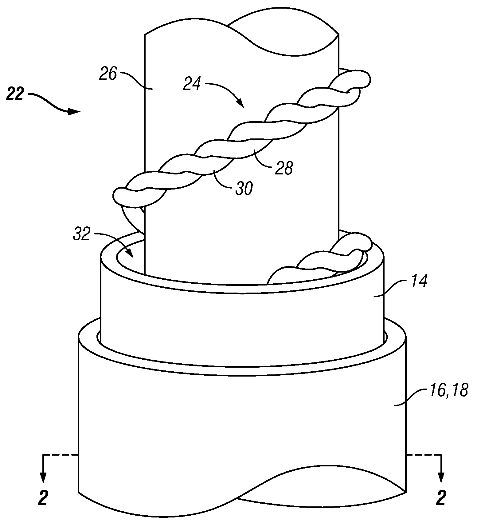
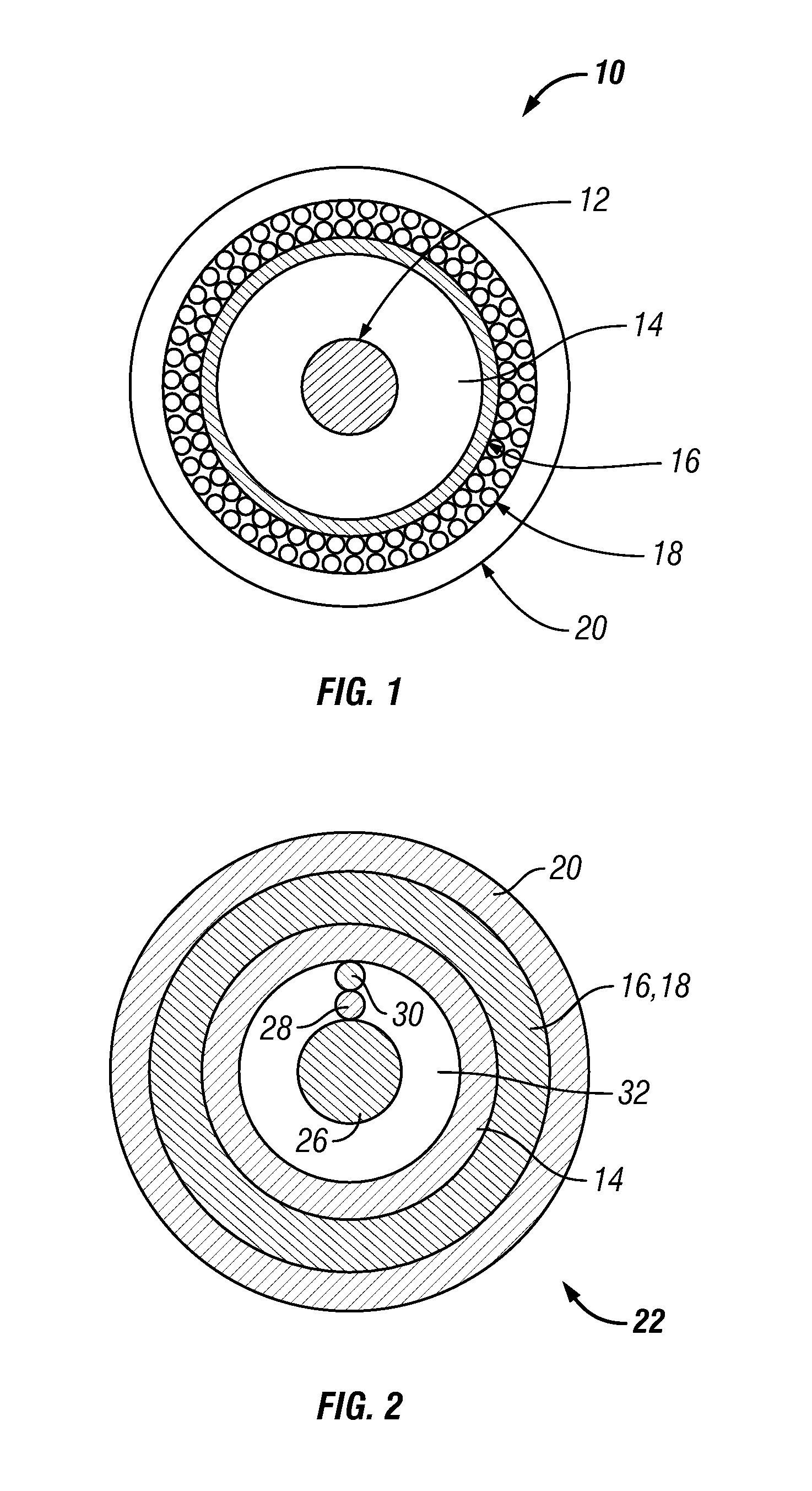
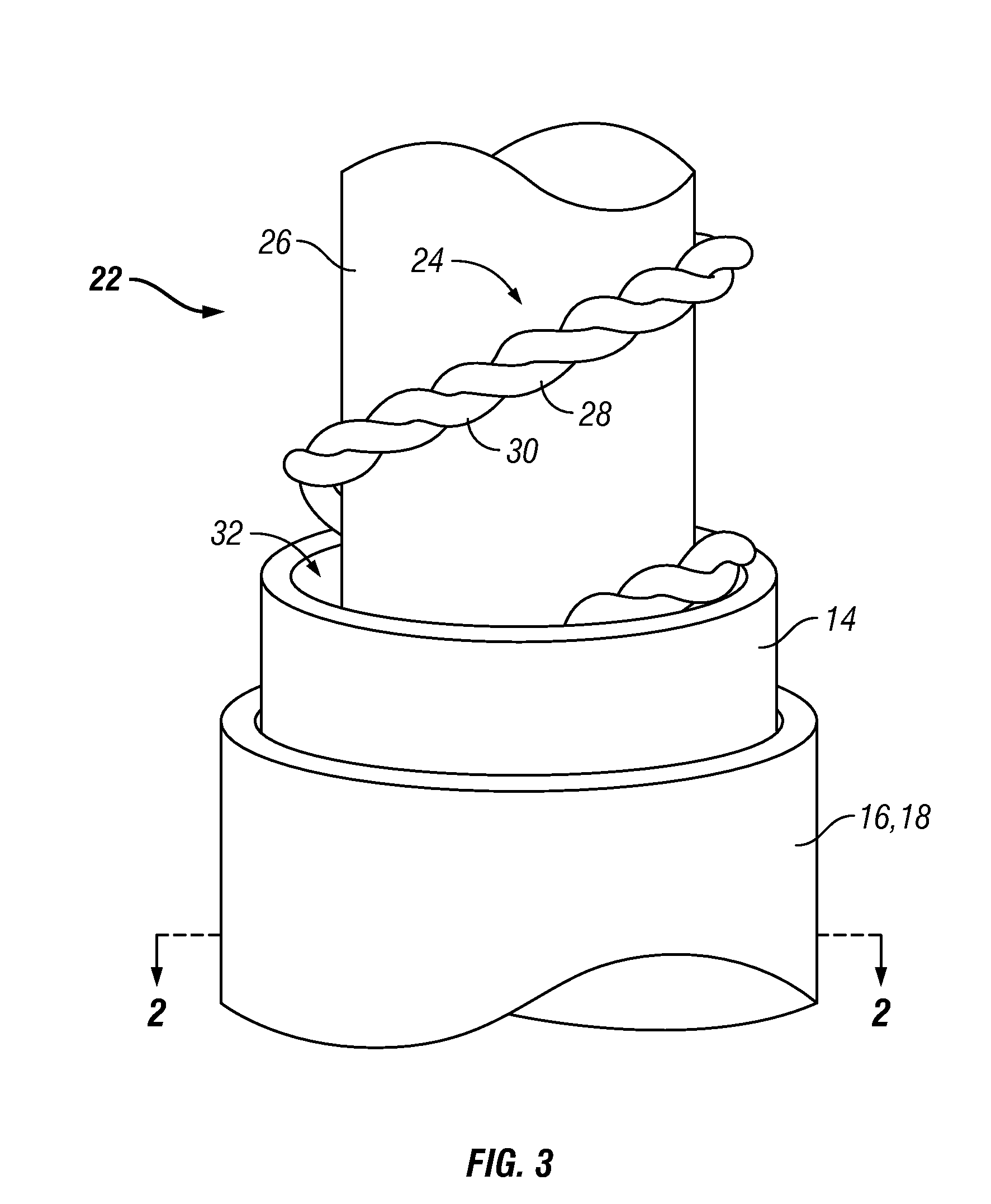
[0035]Central conductor: 24 AWG, 0.0201″ silver-plated copper[0036]Dielectric insulator: High-purity FEP, 0.066″+0.001″ OD[0037]Inner shield: Helically overlapped, flat, silver-plated copper[0038]Braid shield: 40 AWG silver plated copper, >90% coverage[0039]Overall shield diameter: 0.086″ nominal[0040]Outer jacket: FEP, 0.0075″ wall thickness[0041]Impedance: 50±1 Ω[0042]Capacitance: 29 pF / ft[0043]Overall diameter “D”: 0.101″±0.005″

[0044]FIG. 4 shows a comparative graph of the insertion loss (in dB) of equivalent coaxial cables but with different dielectric insulators, as a function of frequency (in Hz). In this context, insertion loss (also known as attenuation) is a measure of the overall decrease in transmitted signal power through a coaxial cable, which results from radiation losses, resistive losses in the conductor, line terminations, losses in the dielectric insulator, etc. Insertion loss is characterized as the ratio of the signal power received by the load (PR) to the ...


PUM

PropertyMeasurementUnit
dissipation factoraaaaaaaaaa
impedance toleranceaaaaaaaaaa
frequenciesaaaaaaaaaa

Abstract

A cable for the ultra high-speed communication of high-frequency signals. The cable includes a longitudinal conductor and an insulator sheath at least partially covering the longitudinal conductor. The cable further includes an inner conductive sheath disposed about an outer periphery of the insulator sheath and an outer insulator jacket disposed about an outer periphery of the inner conductive sheath. The insulator sheath is manufactured from a high-purity fluorinated ethylene propylene.

Description

CROSS-REFERENCE TO RELATED APPLICATION[0001]This application claims the benefit of U.S. Provisional Application Ser. No. 61 / 021,929, filed on Jan. 18, 2008, which is hereby incorporated by reference in its entirety.FIELD OF THE INVENTION[0002]This invention relates to electrical cables and, more specifically, to coaxial-type electrical cables.BACKGROUND OF THE INVENTION[0003]Coaxial cables are a type of electrical cable used most oftentimes to carry high-frequency communication signals, e.g., signals that range from a fraction of a megahertz to tens of gigahertz in frequency. A typical coaxial cable includes a central conductor (or group of conductors), a dielectric insulator covering the central conductor, an inner cylindrical conducting shield or sheath (which is coaxial with the central conductor and which provides a signal reference or ground), and an outer insulating jacket. Ideally, the electromagnetic field carrying the signal exists only in the space between the central con...

Claims


Application Information

Patent Timeline
Patent Type & Authority Applications(United States)
IPC IPC(8): H01B7/00H01B13/20
CPCY10T29/49123H01B11/1847
Inventor PLOURDE, KENNETHPOKLEMBA, RONALDGASEK, JEFFREY
Owner TEMP FLEX L L C
Learn More