
Fluoropolymer-glass fabric for circuit substrates

a technology of fluoropolymer glass and circuit substrate, which is applied in the direction of woven fabrics, textiles and paper, synthetic resin layered products, etc., can solve the problems of defective printed circuits, increased circuit substrate costs, and similar complexity of circuit substrates of u.s. pat. no. 4,886,699, and achieve the effect of improving the adhesion of composite structures

Active Publication Date: 2007-03-01
THE CHEMOURS CO FC LLC +1
View PDF8 Cites 11 Cited by
  • Summary
  • Abstract
  • Description
  • Claims
  • Application Information

AI Technical Summary

Benefits of technology

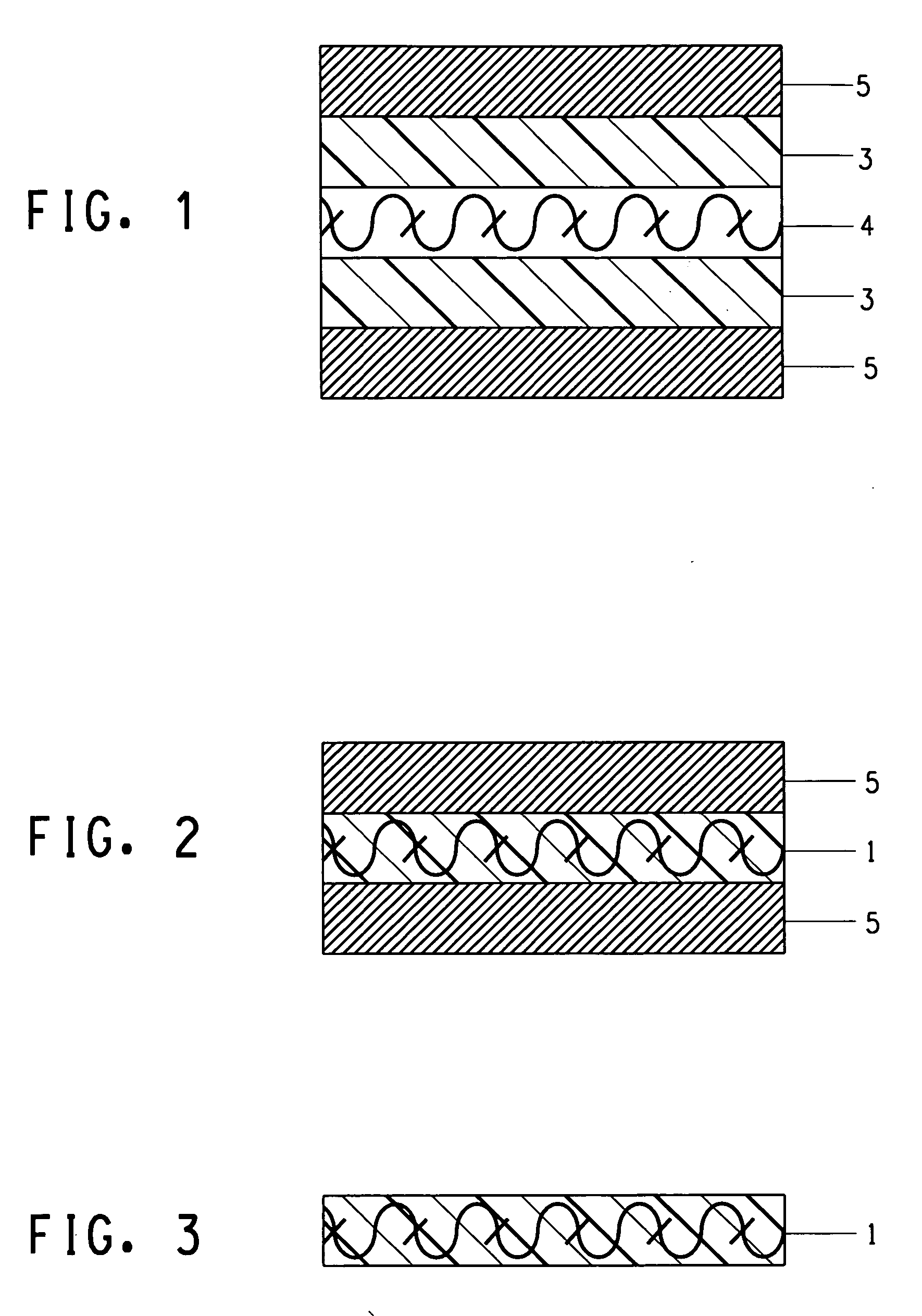
[0007] The present invention satisfies this need by providing a composite structure comprising glass cloth and melt-processable fluoropolymer, the entire thickness of the glass cloth being embedded in the fluoropolymer, said fluoropolymer containing an effective amount of adhesive agent to improve the adhesion of the composite structure to a copper layer by at least 60% as compared to said composite structure wherein said embedded fluoropolymer contains no adhesive agent.
[0008] One advantage of this composite structure is that it is self-adhering to an electrically conductive metal layer, which will typically be copper. No intervening adhesive layer is needed and no surface treatment of either the metal layer or the composite structure is needed to obtain this adhesion between the composite structure and the electrically conductive metal layer. Another advantage of the composite structure is its excellent properties, making it particularly useful as a circuit substrate. The circuit substrate formed by this composite structure has excellent heat resistance, low hygroscopicity, low dielectric constant and low dissipation factor (tan delta), making the circuit substrate suitable for high frequency electric application, and high mechanical strength, low linear expansion coefficient and low thermal shrinkage rate as well as improved dimensional stability. The combination of the fluoropolymer and the glass cloth into a single sheet provides this excellent combination of properties. The composite structure will typically be in the form of a sheet having two opposing planar surfaces, top and bottom surfaces, that can be made to the desired circuit-use size or to a larger size that can be trimmed or cut to the desired size. The composite structure of the present invention preferably has a dielectric constant at a frequency of 10 GHz of no greater than 3.0 and a coefficient of linear expansion of no greater than 25×10−6 / ° C.

Problems solved by technology

However, in order to obtain such base material with sufficient adhesion between the non-melt-flowable PTFE and glass cloth, it is necessary to perform press molding at high temperature under high pressure.
The result of this moisture absorption is that the dielectric constant and dielectric loss tangent of the circuit substrate becomes uneven, rendering the printed circuit defective.
The combination of base layer and adhesive layer to form the circuit substrate increases the cost of the circuit substrate.
The circuit substrate of U.S. Pat. No. 4,886,699 is similarly complicated, i.e. additional layering between the PTFE impregnated glass cloth and the copper circuit-forming layer is provided.

Method used


Image

  • Fluoropolymer-glass fabric for circuit substrates

Examples


application examples

[0055] The present invention will be explained below in more detail with reference to application examples and comparative examples. The present invention, however, is not limited to these examples.

[0056] In the present invention, the various properties were measured using the following methods.

(1) Melting point (Melting Peak Temperature)

[0057] A differential scanning calorimeter (Pyris 1 type DSC, product of Perkin Elmer Corporation) was used. 10 mg of sample powder was weighed and added into an aluminum pan. After the pan is closed by crimping, the sample powder was set in the main body of the DSC, where it was heated from 150° C. to 360° C. at a rate of 10° C. / min. The melting peak temperature (Tm) was derived from the resulting melting curve.

(2) Melt Flow Rate (MFR)

[0058] A melt indexer (made by Toyo Seiki K.K.) equipped with anti-corrosive cylinder, die and piston was used according to ASTM D1238-95. 5 g of sample powder was filled into the cylinder maintained at 372±1° ...

application example 1

[0062] After melt-processable fluoropolymer PFA (product of Mitsui / DuPont Fluorochemical Co., Ltd., melting point 309° C., melt flow rate (372° C., 5 kg load) 36 g / 10 min) and a liquid crystal polymer (Zenite® 6000 produced by DuPont and having a melting temperature of 340° C. and flow temperature of 335° C.) were fully dried, they were melt blended together with a tertiary copolymer (terpolymer) of tetrafluoroethylene, perfluoro(propyl vinyl ether) (PPVE), and CF2═CF[OCF2CF(CF3)]OCF2CF2CH2OH (the functional monomer) used as the functional group containing melt-processable fluoropolymer PFA (PPVE content 3.7 wt %, said hydroxyl containing monomer content 1.1 wt %, melt flow rate 15 g / 10 min) by using a twin screw extruder to generate pellets of the fluoropolymer mixture (melt temperature 365° C.) having a melt flow rate 51 g / 10 min. The melt-processable fluoropolymer pellets had a composition by weight of melt-processable fluoropolymer PFA / liquid crystal polymer / functional group con...

application example 2

[0065] Thermocompression was performed in the same way as described in Application Example 1 except that the lamination structure was changed to copper foil / G / T1 / G / copper foil. A fluoropolymer containing copper-clad laminate with a thickness of about 75 μm used for measuring peel strength (sample S2a) was obtained. Also, the surface of sample S2a was etched to remove the copper foil in order to obtain a sample used for measuring the dielectric constant and the linear expansion coefficient (sample S2b).


PUM

PropertyMeasurementUnit
frequencyaaaaaaaaaa
dielectric constantaaaaaaaaaa
diameteraaaaaaaaaa

Abstract

An improved circuit substrate is provided wherein glass cloth is completely embedded within fluoropolymer by thermocompression to form a composite structure, which when containing an adhesive agent such as the combination of functional groups and liquid crystal polymer is self-adhering to a metal layer such as of copper.

Description

FIELD OF THE INVENTION [0001] This invention relates to circuit substrates for supporting and dimensionally stabilizing printed circuits, while providing good electrical insulation between circuits, and in particular to the use of fluoropolymer and glass fabric to provide such substrate. BACKGROUND OF THE INVENTION [0002] In the field of electrical and electronic parts, along with development of miniaturized devices with high performance and high density, it is desired to develop circuit substrate materials with excellent heat resistance, dimensional stability, low hygroscopicity, adhesion to copper foil, and good high frequency characteristics. [0003] Fluoropolymers can be used in circuit substrates since they have low dielectric constants. Although many fluoropolymer-based materials for high frequency circuit substrates have been proposed (U.S. Pat. No. 3,139,515, Japanese Kokai Patent Application No. Hei 8[1996]-276547, Sho 62[1987]-261190) to meet the demands of the high-frequen...

Claims


Application Information

Patent Timeline
Patent Type & Authority Applications(United States)
IPC IPC(8): B32B17/02B32B27/04B32B5/02
CPCB32B5/024H05K2201/015B32B15/08B32B15/082B32B15/085B32B15/20B32B27/04B32B27/12B32B27/304B32B27/322B32B2262/101B32B2307/202B32B2307/204B32B2307/306B32B2307/31B32B2307/518B32B2307/538B32B2307/5825B32B2307/714B32B2307/734B32B2457/08C08J5/04C08J5/24C08J2327/12H05K1/034H05K1/0366H05K2201/0141B32B7/08Y10T442/2475Y10T442/656Y10T428/3154Y10T442/3415Y10T442/2418Y10T442/20Y10T442/475Y10T428/31678Y10T442/2992C08J5/244H05K1/03
Inventor LEE, JEONG CHANGTAKI, ETSUYA
Owner THE CHEMOURS CO FC LLC
Learn More