[0008]Therefore, an object of the present invention is to provide a joining structure of tank components capable of suppressing the generation of foreign matter due to abrasion or cutting of a bearing surface. Another object is to provide a joining structure of tank components capable of preventing the foreign matter from entering into a tank via the opening of a mouthpiece even when it is generated.
[0011]The fastening force of the tank component (e.g., a valve assembly) in a thrust direction is preferably kept constant. Usually, the valve assembly is fastened with a
constant torque to obtain a constant fastening force (so-called torque management). However, for example, when the valve assembly is once detached and attached again for inspection, foreign matter is sometimes interposed between the bearing surfaces, or the bearing surfaces are damaged. In a case where the valve assembly is fastened as it is, even when a
constant torque is given, the fastening force sometimes cannot be kept constant. On the other hand, according to the joining structure of the present invention, the
surface layer of at least one of the bearing surfaces which come in contact with each other is formed of the layer having the abrasion resistance larger than that of the base material, so that during, for example, the joining of the tank components, the damage on the bearing surfaces which come in
sliding contact with each other can be suppressed. Moreover, when the bearing surfaces come in
sliding contact with each other, the generation of foreign matter such as fine cutting residue or dust can be suppressed.
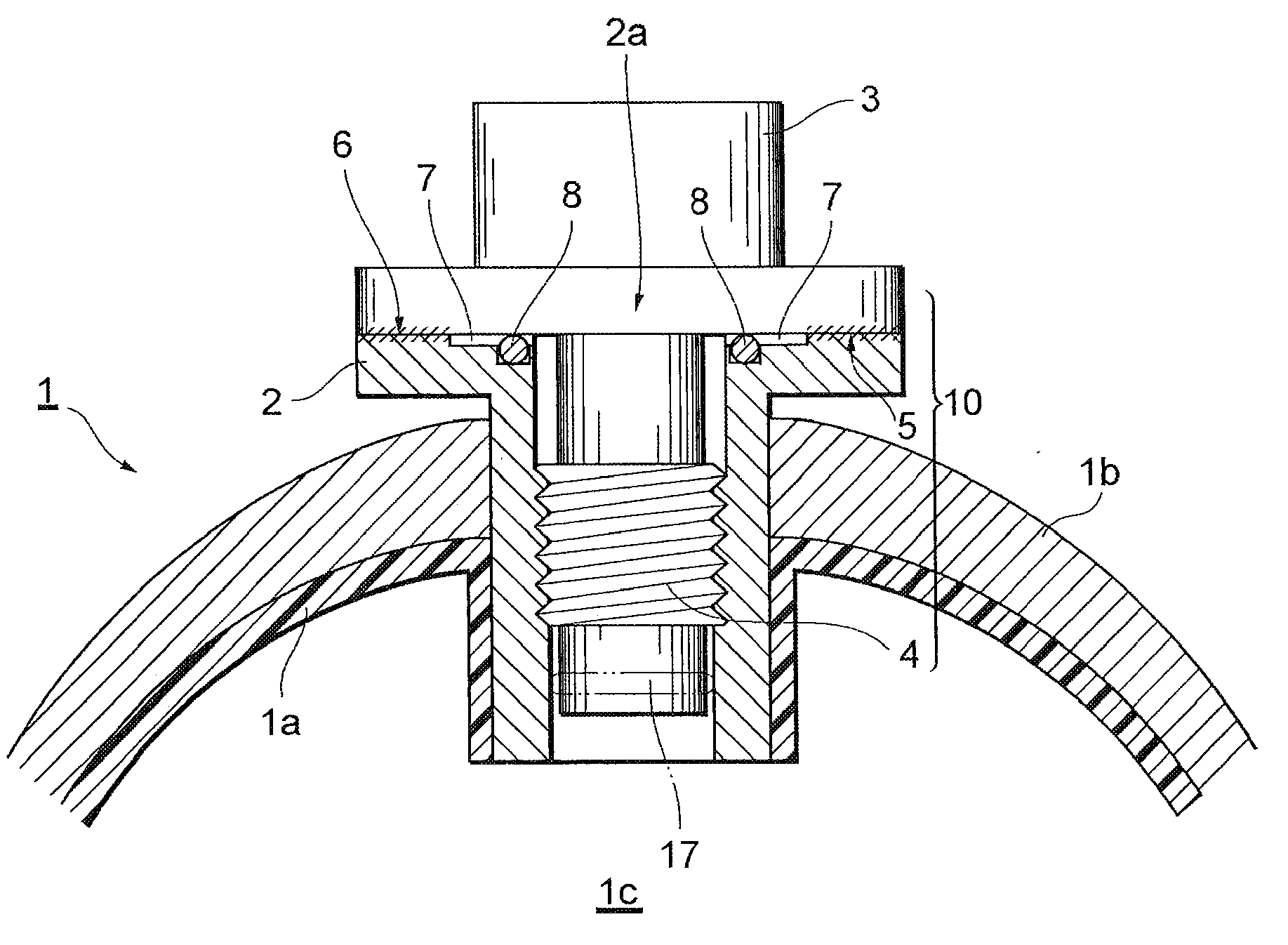
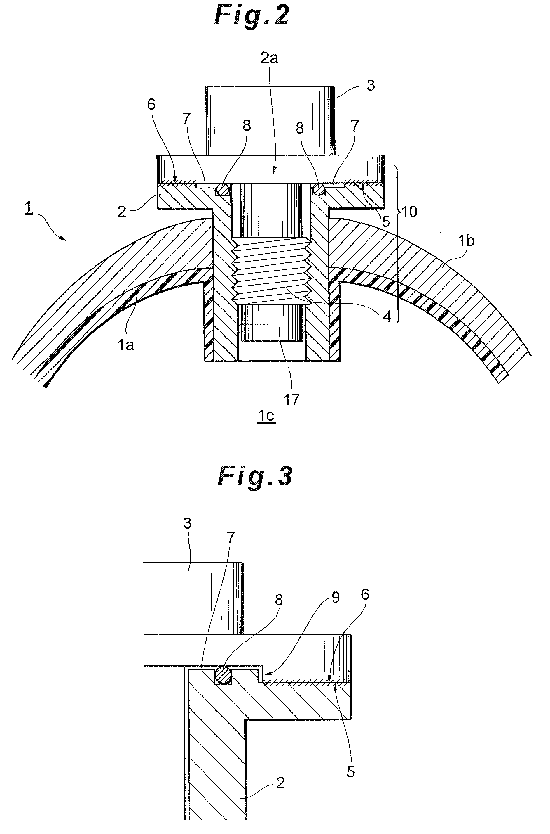
[0014]In addition, according to the present invention, there is provided a joining structure of tank components to be joined to a mouthpiece of a high-pressure tank, comprising: a screw joining unit to be joined to the mouthpiece; a tank component side bearing surface which axially comes in contact with the mouthpiece; a mouthpiece side bearing surface which comes in contact with the tank component side bearing surface; a recess provided on the inner
peripheral side of a portion where the tank component side bearing surface and the mouthpiece side bearing surface come in contact with each other and on the outer peripheral side of an opening of the mouthpiece so as to form a space between the tank component and the mouthpiece; and a foreign matter intrusion suppressing seal member provided in the recess so as to prevent the intrusion of foreign matter into the opening of the mouthpiece. In this case, the surface of at least one of the tank component side bearing surface and the mouthpiece side bearing surface is preferably subjected to an abrasion resisting treatment.
[0015]In this joining structure, for example, an annular recess is formed around the opening of the mouthpiece, and an annular bearing surface (a surface
abutment portion between the tank component and the mouthpiece) is further formed around the recess. In this case, the recess which forms the space between the tank component and the mouthpiece functions so that the tank component does not come in
sliding contact with the mouthpiece. That is, the recess functions so that any foreign matter is not generated around the opening. Therefore, in such a joining structure, if the foreign matter (cutting residue, burrs, dust, etc.) sometimes generated at a time when the outer peripheral bearing surfaces (surface
abutment portions) come in sliding contact with each other intrude into the opening of the mouthpiece, the foreign matter has to pass through the space. In the present invention, the seal member provided in this space suppresses the intrusion of the foreign matter into the opening of the mouthpiece. Moreover, in a case where at least one of the bearing surfaces which come in contact with each other is subjected to the abrasion resisting treatment, it can be prevented that the bearing surfaces are damaged or that foreign matter is generated owing to the sliding contact.
[0016]Furthermore, it is also preferable that a foreign matter intrusion suppressing stepped portion to suppress the intrusion of the foreign matter into the opening of the mouthpiece is formed on the inner peripheral side of the portion where the tank component side bearing surface and the mouthpiece side bearing surface come in contact with each other and on the outer peripheral side of the opening of the mouthpiece. The stepped portion formed in this manner can function as a stopper to prevent the foreign matter from reaching the opening of the mouthpiece, even when the foreign matter is generated owing to the sliding contact between the bearing surfaces.

