Sterilizing apparatus

Active Publication Date: 2009-07-23
PHC HLDG CORP
View PDF3 Cites 24 Cited by
  • Summary
  • Abstract
  • Description
  • Claims
  • Application Information

AI Technical Summary

Benefits of technology

[0013]According to the second aspect of the invention, in the first aspect, since the sterilizing gas generator atomizes the sterilizer solution by means of the ultrasonic vibrator, it is possible to atomize a sundry germs sterilizer and fill the chamber with the atomized sterilizer as a gas without decomposing the sterilizer, unlike a heat and atomization method. Accordingly, it is possible to efficiently sterilize the inside of the apparatus and the articles.
[0014]According to the third aspect of the invention, in the first aspect, since the sterilizing gas generator evaporates the sterilizer solution by dipping the absorbing member into the sterilizer solution, it is possible to effectively generate the sterilizing gas to sterilize the articles and the inside of the apparatus while simplifying the configuration of the apparatus.
[0015]According to the fourth aspect of the invention, in one of the first to third aspects, since the sterilizing gas concentration in the chamber is from 0.1 ppm to 100 ppm, it is possible to reliably sterilize the articles and the inside of the apparatus.
[0016]According to the fifth aspect of the invention, in one of the first to fourth aspects, since the sterilizing apparatus further includes the ultraviolet generator that irradiates gas in the chamber with the ultraviolet ray, it is possible to quickly lower the concentration of the sterilizing gas to a concentration harmless to a human body by decomposing the sterilizing gas using the ultraviolet ray after sterilizing the articles and t

Problems solved by technology

However, the above-mentioned article sterilizing method requires a plurality of spraying devices, which may result in a large-scale

Method used


Image

  • Sterilizing apparatus
  • Sterilizing apparatus
  • Sterilizing apparatus

Examples


Example

Embodiment 1

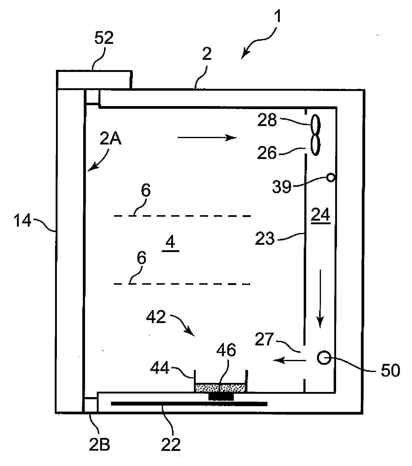
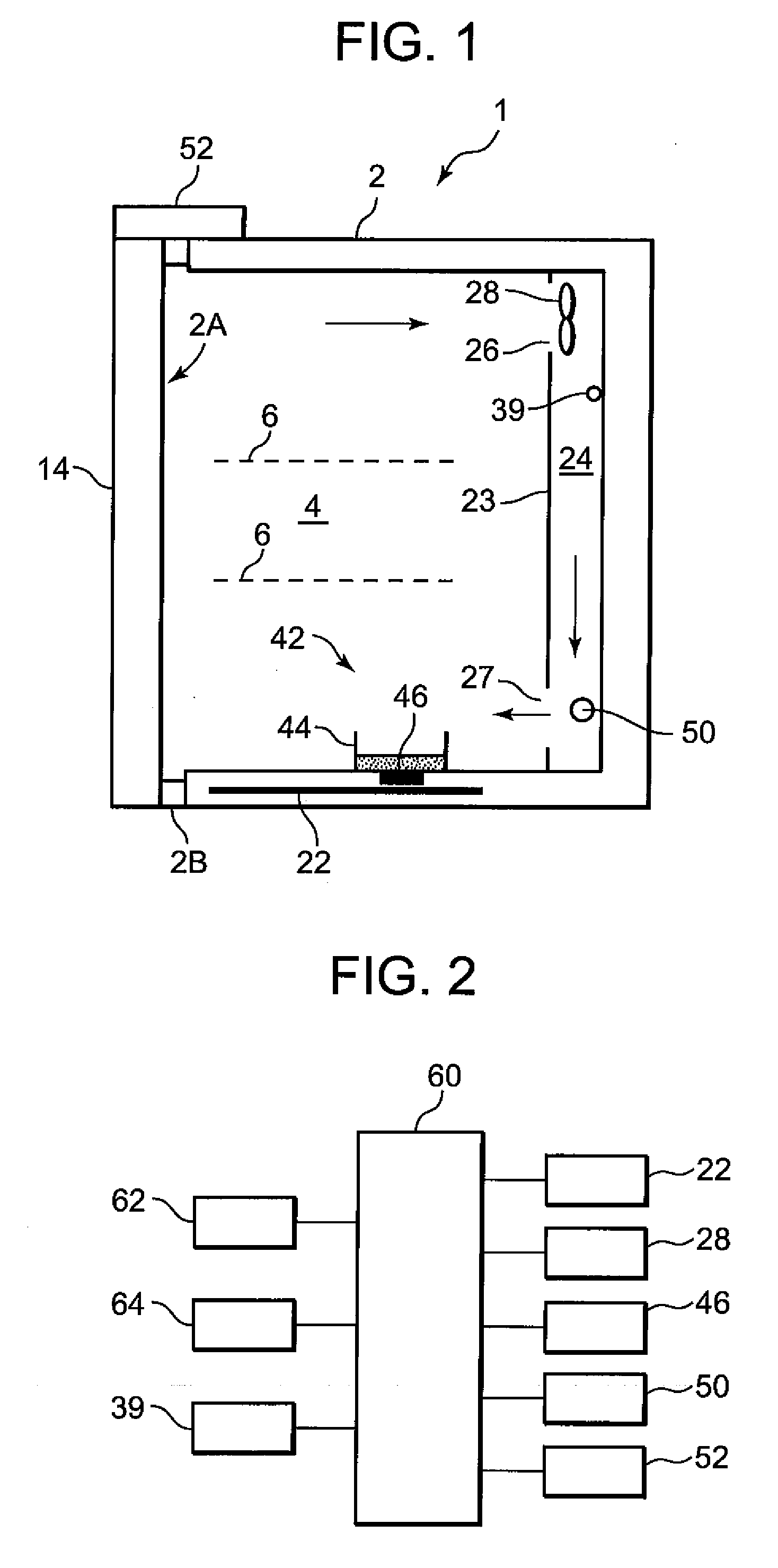
[0023]Hereinafter, embodiments of the present invention will be described with reference to the drawings. FIG. 1 is an end side view showing a structure of a sterilizing apparatus 1 according to an embodiment of the present invention, and FIG. 2 is a block diagram of a control circuit for controlling the sterilizing apparatus 1 of the present invention.

[0024]In this embodiment, as shown in FIG. 1, the sterilizing apparatus 1 includes a double-hollow-structured metal (stainless steel) box body 2 having an opening 2A at one side thereof. In addition, the opening 2A of the box body 2 is provided with a door 14 whose right side is supported to the box body 2 by a hinge in a free-opening / closing manner. The door 14 blocks the opening 2A air-tightly by means of a gasket 2B provided in the opening 2A of the box body 2.

[0025]A chamber 4 is formed in a space surrounded by the door 14 blocking the opening 2A in a free-opening / closing manner. Within the chamber 4 are provided a plu...

Example

Embodiment 2

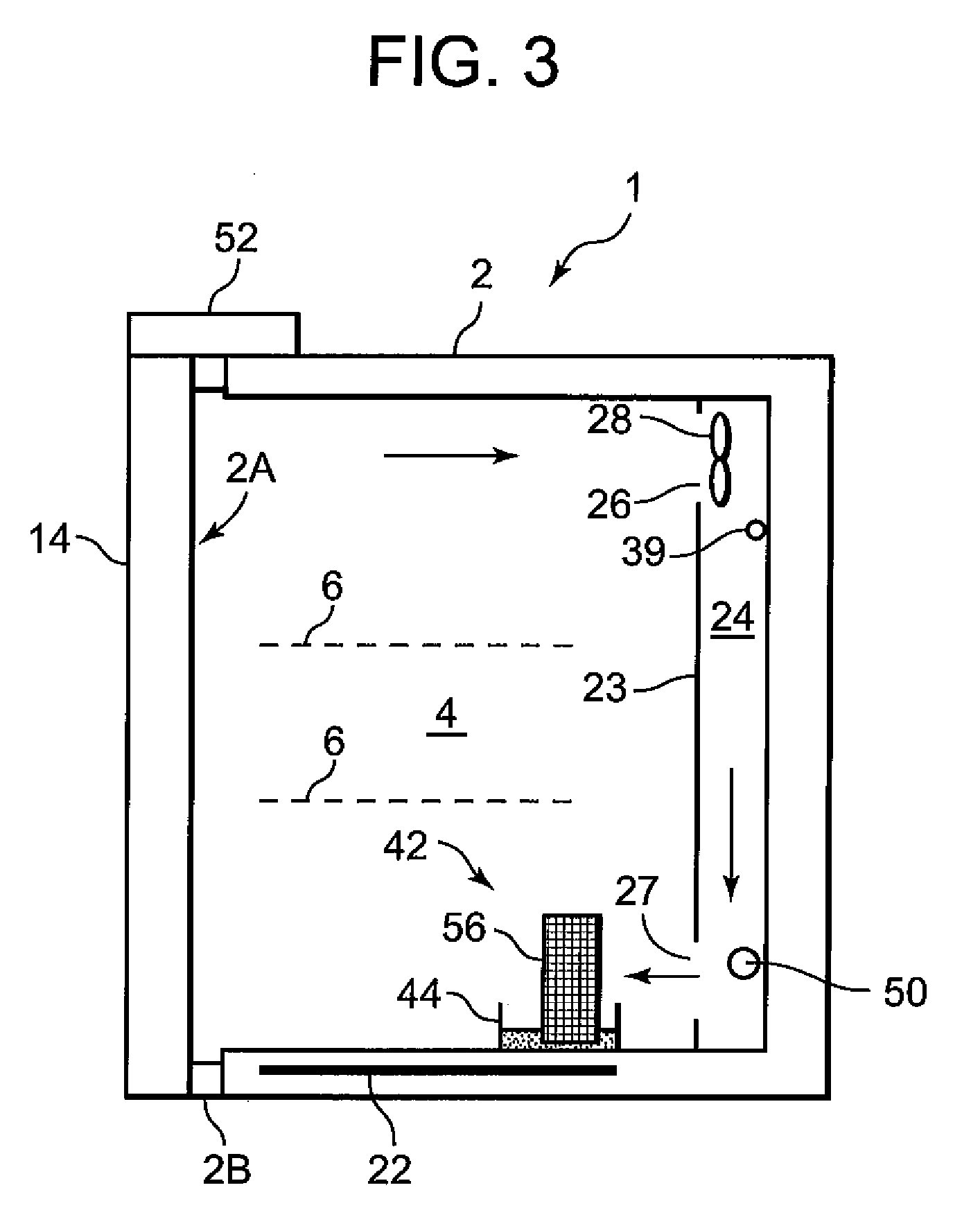
[0045]Next, FIG. 3 shows a sterilizing apparatus 1 according to another embodiment of the present invention. The sterilizing apparatus 1 of this embodiment has substantially the same configuration as the above-described embodiment. Hereinafter, only portions different from the above-described embodiment will be described. In the figure, the same elements as the above-described embodiment are denoted by the same reference numerals, and explanation of which will be omitted. As shown in FIG. 3, in the sterilizing apparatus1, the ultrasonic vibrator 46 of the sterilizing gas generator 42 in Embodiment 1 is replaced with an absorbing member 56. When the absorbing member 56 is dipped into oxygenated water, the oxygenated water is evaporated.

[0046]That is, the sterilizing gas generator 42 is provided with the absorbing member 56 erecting in the vessel 44 having flat bottom. A frame (not shown) made of stainless steel or synthetic resin is provided around the absorbing member 56...


PUM

PropertyMeasurementUnit
Fractionaaaaaaaaaa
Fractionaaaaaaaaaa
Currentaaaaaaaaaa

Abstract

There is provided a sterilizing apparatus which is capable of sterilizing articles, such as test tubes, flasks, beakers, scalpels, forceps and so on, with high efficiency in a short time. The sterilizing apparatus includes a sterilizing gas generator 42 that supplies sterilizing gas into a chamber 4. The sterilizing gas generator 42 atomizes a sterilizer solution (oxygenated water) by means of an ultrasonic vibrator 46. The sterilizing apparatus further includes an ultraviolet generator (ultraviolet lamp 50) that irradiates gas in the chamber 4 with an ultraviolet ray. The sterilizing apparatus further includes a door 14 for blocking an opening 2A of the chamber 4 in a free-opening/closing manner and a locking device 52 for prohibiting the door 14 from being opened. The sterilizing apparatus further includes a controller 60 for controlling the locking device 52 to prevent the door 14 from being opened from start of the sterilization process to end of the decomposition process.

Description

BACKGROUND OF THE INVENTION[0001]This invention relates to a sterilizing apparatus for sterilizing articles received in a chamber.[0002]In the related art, when articles such as vessels are to be cleaned, a water / air mixture is sprayed into the articles by means of a water / air mixture spraying device, distilled water is sprayed into the articles by means of a distilled water spraying device, and then sterile water is sprayed into the articles by means of a sterile air spraying device. In that manner, the articles are sterilized and cleaned (see Japanese Patent Application Publication No. 2005-279648).[0003]However, the above-mentioned article sterilizing method requires a plurality of spraying devices, which may result in a large-scale system. In addition, the distilled water provides insufficient cleaning and thus an insufficient sterilizing effect for the articles.SUMMARY OF THE INVENTION[0004]The present invention has made to overcome such a conventional problem and it is an obje...

Claims


Application Information

Patent Timeline
IPC IPC(8): A61L2/20
CPCA61L2/208A61L2202/122A61L2/24A61L2/22A61L2/16A61L2/20
Inventor BUSUJIMA, HIROKI
Owner PHC HLDG CORP
Why Eureka
Try Eureka