Inorganic phosphor

a technology of organic phosphor and phosphorus, which is applied in the field of organic phosphor, can solve the problems of low luminescence efficiency of brochures, limited luminescence wavelength regions, and limited use, and achieve the effect of sufficient luminous efficiency and sufficient luminous efficiency

Inactive Publication Date: 2009-07-23
FUJIFILM CORP
View PDF2 Cites 0 Cited by
  • Summary
  • Abstract
  • Description
  • Claims
  • Application Information

AI Technical Summary

Benefits of technology

[0013]Under the above-described circumstances, a phosphor has been desired to develop which has a novel luminescent center, which can be applied to a luminescence device capable of being driven by either of direct current and alternating current, and which can provide sufficient luminous efficiency.
[0014]Therefore, the present invention provide an inorganic phosphor which has a novel luminescent center, which can be applied to a luminescence device capable of being driven by either of direct current and alternating current, and which can provide sufficient luminous efficiency, a luminescence device using the same, and a direct current thin-film type inorganic EL element.

Problems solved by technology

However, the direct current-driving type inorganic EL element described in the International Publication No. 2007 / 043676, pamphlet has a low luminous efficiency and its luminescence wavelength region is limited.
However, D-A pair light emission type inorganic phosphors involve the problem that, since they can be applied only to alternating current-driving type luminescence device, its use is limited.
Further, the phosphor described in JP-A-2006-199794 is considered to be of a localized light emission type using a rare earth sulfide as a host material wherein Mn and / or Pr is localized, but such localized light emission type materials wherein Mn or rare earth element is localized involves the problem that they fail to provide sufficient luminous efficiency though they can be applied to luminescence devices capable of being driven by either of direct current and alternating current.

Method used


Image

  • Inorganic phosphor
  • Inorganic phosphor

Examples


example 1

[0079]Ir2(SO4)3 is weighed and mixed with ZnS in an amount shown below per 100 g of ZnS in terms of Ir element amount based on Zn element amount. After mixing in a mortar for 20 minutes or more, the mixture is calcined in vacuo at 1100° C. for 3 hours. After the calcination, the product is pulverized, washed with water, and dried to obtain an Ir-containing ZnS phosphor.

[0080]The wavelength and intensity of emitted light by photoluminescence (PL) upon excitation of the thus-obtained phosphor with 330-nm ultraviolet rays are shown in the following Table 1.

TABLE 1Wavelength ofIntensity ofDoping Amount ofEmitted Light byEmitted Light byIr2(SO4)3PLPLNotesSample A0No emission ofNo emission ofComparativelightlightExampleSample B1E−7 mol / mol Zn445 nm100Present InventionSample C1E−6 mol / mol Zn445 mn800Present InventionSample D1E−5 mol / mol Zn445 nm3200Present InventionSample E1E−4 mol / mol Zn445 nm1800Present InventionSample F1E−3 mol / mol Zn460 nm56Present InventionSample G1E−2 mol / mol Zn458 n...

example 2

[0083]A XIII Group-XV Group compound shown below is added in an amount also shown below to sample D described in Example 1, followed by mixing and calcining in vacuo at 700° C. for 6 hours. The results are shown in the following Table 2.

TABLE 2Doping AmountDoping Amount of XIIIof Ir2(SO4)3Group-XV Group CompoundSample I1E−5 mol / mol ZnInP; 2E−4 mol / mol ZnSample J1E−5 mol / mol ZnInSb; 2E−4 mol / mol ZnSample K1E−5 mol / mol ZnGaN; 2E−4 mol / mol Zn

[0084]It can be seen that emission of light by doping with Ir is more enhanced by the addition of the XIII Group-XV Group compound (comprising an element belonging to the Group 13 and an element belonging to the Group 15 of the periodic table). In particular, addition of InSb provides the highest PL light emission.

example 3

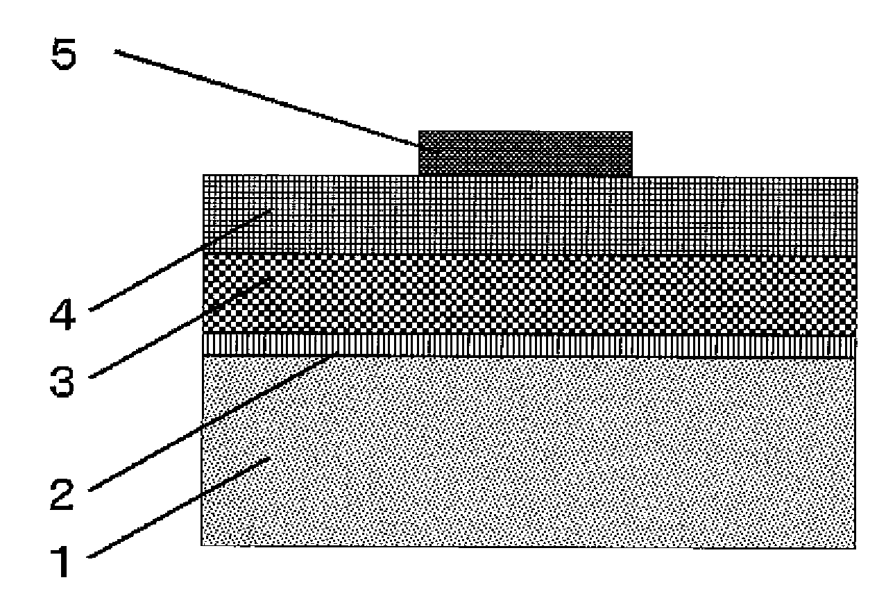
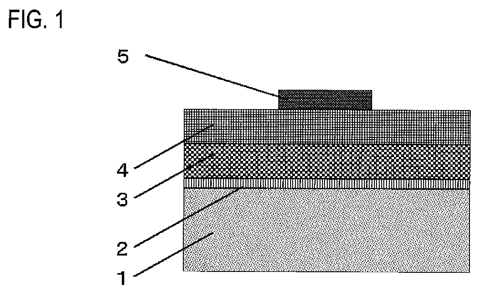
[0085]A direct-current driving type inorganic EL element is prepared by using the inorganic phosphor of samples D and H to K obtained in Examples 1 and 2 as inorganic fluorescent material. The structure of the direct-current driving type inorganic EL element is schematically shown in FIG. 1

[0086]A transparent electrode comprising a transparent glass substrate 1 having formed thereon a first electrode 2 of ITO in a thickness of 200 nm by sputtering is used as a substrate, and the inorganic phosphor of samples D and H to K each is vacuum-deposited to form a film on the substrate by means of an EB vacuum deposition apparatus. More specifically, the inorganic phosphor is disposed as a first vacuum deposition source, and selenium metal is disposed as a second vacuum deposition source. Vacuum deposition from the first vacuum deposition source is conducted at a constant film-forming rate, whereas vacuum deposition from the second vacuum deposition source in the former half of film formatio...


PUM

PropertyMeasurementUnit
voltageaaaaaaaaaa
frequencyaaaaaaaaaa
voltageaaaaaaaaaa

Abstract

An inorganic phosphor includes: a host material that contains at least one host compound selected from the group consisting of compounds of group 2 element with group 16 element of the periodic table and compounds of group 12 element with group 16 element of the periodic table, or a mixed crystal of the host compound; and a dopant that includes at least one metal element selected from the group consisting of first metal elements belonging to second transition series of from group 6 to group 11 of the periodic table and second metal elements belonging to third transition series of from group 6 to group 11 of the periodic table, and does not include Cu and Mn.

Description

BACKGROUND OF THE INVENTION[0001]1. Field of the Invention[0002]The present invention relates to an inorganic phosphor (hereinafter it is also referred to as an inorganic fluorescent material) useful for, for example, an alternating current dispersion-type inorganic EL element, an alternating current thin film-type inorganic EL element, and a direct current thin film-type inorganic EL element.[0003]2. Description of the Related Art[0004]Fluorescent materials are materials which emit light when an energy such as light, electricity, pressure, heat, or electron beams is applied thereto, and are materials which have long been known. Among them, those fluorescent materials which include an inorganic material have been used for a TV tube, a fluorescent lamp, an electroluminescence (EL) element, or the like due to the luminescence properties and stability thereof. In recent years, application thereof to low-speed electron excitation such as in PDP as a color conversion material for use in ...

Claims


Application Information

Patent Timeline
Patent Type & Authority Applications(United States)
IPC IPC(8): B32B9/00C09K11/54
CPCC09K11/565C09K11/567C09K11/873H05B33/18C09K11/883C09K11/885H05B33/14C09K11/876C09K11/75C09K11/88
Inventor SHIRATA, MASASHI
Owner FUJIFILM CORP
Why Eureka
Try Eureka