Organic Electroluminescent Element, Compound for Use in the Element, and Light Emitting Device, Display Device, and Illumination Device Using the Element

a technology of electroluminescent elements and compounds, applied in the field of organic electroluminescent elements, can solve the problems of poor chromaticity and insufficient performance (including luminous efficiency) of light emitting materials, and achieve excellent chromaticity, sufficient luminous efficiency, and sufficient luminous efficiency.

Active Publication Date: 2018-03-08
UDC IRELAND
View PDF0 Cites 0 Cited by
  • Summary
  • Abstract
  • Description
  • Claims
  • Application Information

AI Technical Summary

Benefits of technology

[0011]Accordingly, there is a need for an organic electroluminescent element that has sufficient luminous efficiency and excellent chromaticity.
[0013]Upon further studies, the present inventors found that sufficient performance as light emitting material can be imparted when a pyrene compound does not have an electron donating group in the substituents across the pyrene ring on the long axis of the pyrene ring, but has an electron donating substituent in the substituents across the pyrene ring on the short axis of the pyrene ring. It was also found that high heat resistance can be imparted when no fused ring structure is formed by the binding of the substituents across the pyrene ring on the short axis of the pyrene ring and any other substituent of the pyrene ring.
[0035]The organic electroluminescent element of the present invention has sufficient luminous efficiency and excellent chromaticity. The organic electroluminescent element having sufficient luminous efficiency and excellent chromaticity can easily be produced by using compounds of the present invention as light emitting material of a light emitting layer. Another advantage is that the light emitting device, the display device, and the illumination device of the present invention have small power consumption, and excellent chromaticity.

Problems solved by technology

It was also found that the pyrene compounds described in KR10-2011-0057008, and the compounds described in JP-A-2009-283899 did not have sufficient performance (including luminous efficiency) as light emitting material, and had poor chromaticity.

Method used


Image

  • Organic Electroluminescent Element, Compound for Use in the Element, and Light Emitting Device, Display Device, and Illumination Device Using the Element
  • Organic Electroluminescent Element, Compound for Use in the Element, and Light Emitting Device, Display Device, and Illumination Device Using the Element
  • Organic Electroluminescent Element, Compound for Use in the Element, and Light Emitting Device, Display Device, and Illumination Device Using the Element

Examples


example 1

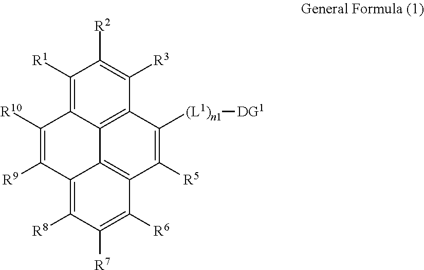
1. Synthesis of Compounds Represented by General Formula (1)

[0323]The compounds represented by the general formula (1) can be synthesized by a combination of known reactions, including the methods descried in JP-A-2009-283899, and JP-A-2006-298793. The following describes representative examples of specific synthesis procedures for the compounds represented by the general formula (1).

Synthesis of Compound 1

[0324]

Synthesis of Compound 1a

[0325]Bromine (26 ml) was dropped onto a dichloromethane solution (500 ml) of 1,2,3,6,7,8-hexahydropyrene (ALDRICH; 50 g) at room temperature, and the mixture was stirred for 4 hours. The precipitated crystals were filtered, and washed with ethanol and hexane to obtain compound 1a (39 g).

Synthesis of Compound 1b

[0326][1,1′-bis(Diphenylphosphino)ferrocene]palladium(II)dichloride (PdCl2(dppf); 0.8 g) was added to a toluene solution (60 ml) of compound 1a (5 g), bispinacoldiborane (17.4 g), and potassium acetate (4 g), and the mixture was stirred under n...

example 2

Production and Evaluation of Organic Electroluminescent Element

[0332]The materials used for the production of the organic electroluminescent element were all purified by sublimation, and the purity (absorption intensity area ratio at 254 nm) was confirmed to be 99.9% or higher by high-performance liquid chromatography (Tosoh TSK gel ODS-100Z).

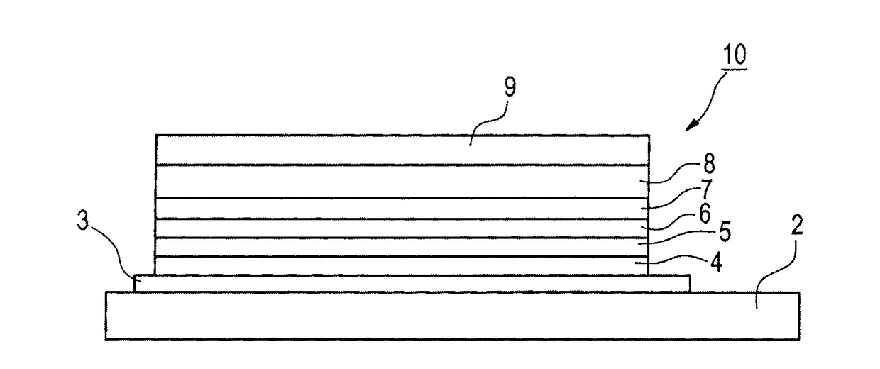
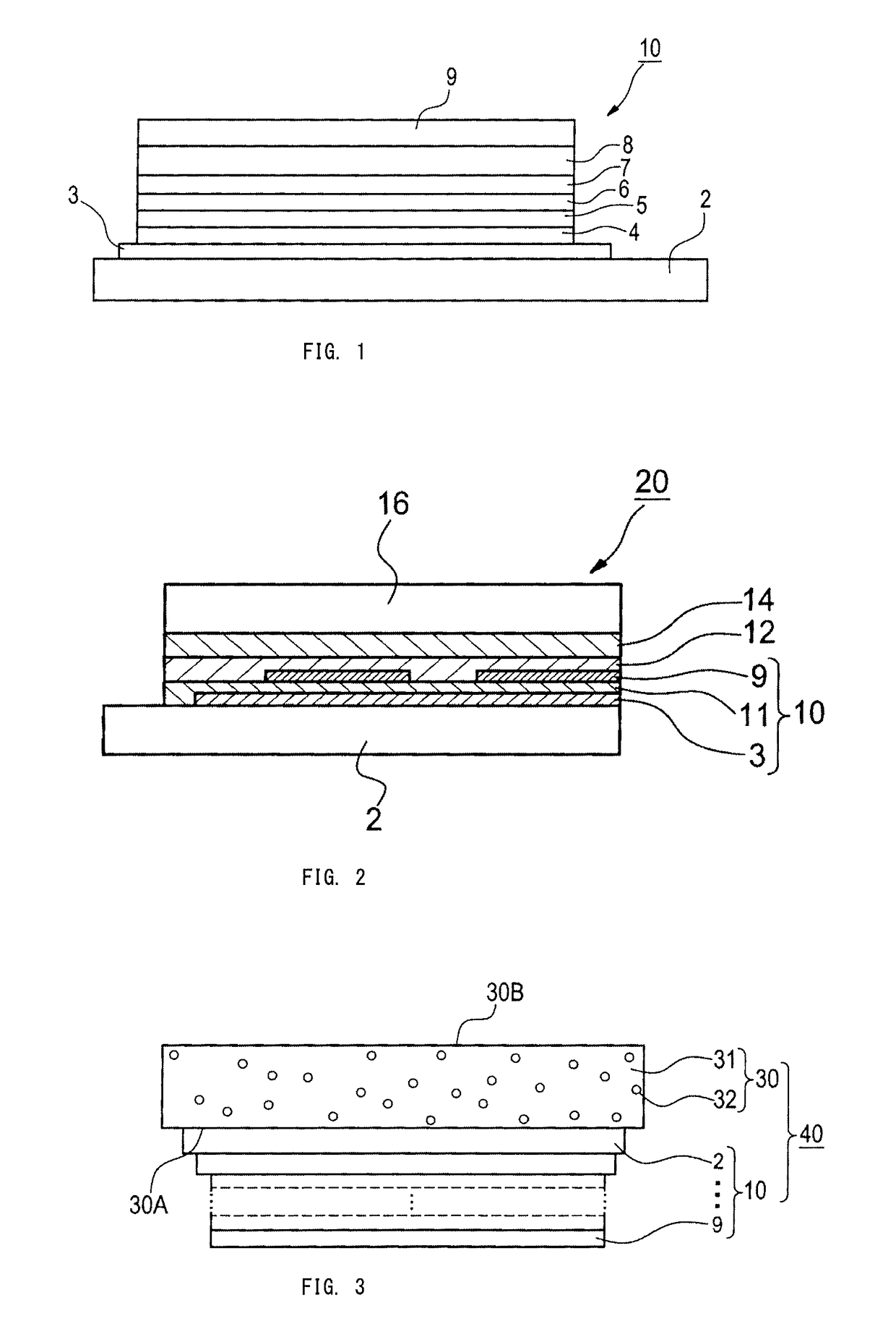
[0333]A 0.5 mm-thick and 2.5 cm square glass substrate (product of Geomatec Co., Ltd., surface resistance: 10 Ω / quadrature) having an ITO film thereon was put in a cleaning container. After ultrasonic cleaning in 2-propanol, the glass substrate was subjected to a UV-ozone treatment for 30 minutes. The following organic compound layers were deposited sequentially on the transparent anode (ITO film) by a vacuum deposition method.

[0334]Note that the deposition rate in the Examples and Comparative Examples below is 0.1 nm / sec unless otherwise specifically indicated. The deposition rate was measured using a quartz oscillator. In addition, the thickn...

example 3

[0345]Organic electroluminescent elements 2-1 to 2-11 and comparative elements 2-1 to 2-4 were produced in the same manner as in Example 2, except that the layer configurations were changed as follows. Evaluations were carried out in the same manner as in Example 2. The results are presented in Table 3 below. Note that the external quantum efficiency shown in Table 3 below is shown as a relative value, taking the value of the comparative element 2-1 (organic electroluminescent element using comparative compound 1) as 1.0.

First layer: HT-4: thickness 50 nm

Second layer: HT-3: thickness 45 nm

Third layer: H-2 and light emitting material (mass ratio=95:5) shown in Table 3: thickness 25 nm

Fourth layer: ET-5: thickness 5 nm

Fifth layer: ET-3: thickness 20 nm

TABLE 3RelativeChromaticityLightexternalafteremittingquantumdeteriorationElement No.materialefficiencyChromaticityby drivingNoteElement 2-1Compound 11.1GoodGoodPresentInventionElement 2-2Compound 31.2GoodGoodPresentInventionElement 2-3Co...


PUM

PropertyMeasurementUnit
luminous wavelengthaaaaaaaaaa

Abstract

The disclosure relates to organic electroluminescent elements, compounds for use in the elements, and devices using the elements, which include a compound represented by the following General Formula (1):where R1 to R3 and R6 to R8 each independently represents a hydrogen atom, which may be a deuterium atom, or a substituent with a Hammett substituent constant σp value of −0.15 or more, R5, R9 and R10 each independently represents a hydrogen atom or a substituent, L1 represents a divalent linking group, DG1 represents a donor group, and n1 represents 1 or 2, and where R1 to R3, R5 to R10, L1, and DG1 are not bound to each other to form a ring.

Description

CROSS-REFERENCE TO RELATED APPLICATIONS[0001]This application claims the benefit of priority to Japanese Patent Application No. 2011-252533, filed Nov. 18, 2011, which is incorporated herein by reference in its entirety.FIELD OF THE INVENTION[0002]The present invention relates to organic electroluminescent elements, and compounds usable therefor. The present invention also relates to light emitting devices, display devices, and illumination devices using the organic electroluminescent elements.BACKGROUND ART[0003]Since organic electroluminescent elements (which may hereinafter also be referred to as “elements” or “organic EL elements”) are capable of high-luminance light emitting using low voltage driving, they have been actively researched and developed. The organic electroluminescent elements have a pair of electrodes and an organic layer between the pair of electrodes, and utilize, for light emitting, energy of the exciton generated as a result of recombination of the electron in...

Claims


Application Information

Patent Timeline
Patent Type & Authority Applications(United States)
IPC IPC(8): H01L51/00C07D401/10C07C211/54C07C211/58C07D213/74C07D239/42C07D241/20C07D495/04C07D493/04C07D333/36C07D307/91C07D307/66C07D263/48
CPCC07C211/54H01L51/0054C07C2603/50C07D307/91C07D307/66C07D495/04C07D493/04C07D263/48C07D241/20C07D239/42C07D401/10C07D333/36C07D213/74C07C211/58H01L2251/308H01L51/0068H01L51/0067H01L51/0065H01L51/0061H01L51/006H01L51/0058H10K85/622H10K85/653H10K85/636H10K85/626H10K85/633H10K85/655H10K85/654H10K2102/103
Inventor TAKAKU, KOJIYONEKUTA, YASUNORISOTOYAMA, WATARUYOUFU, KATSUYUKIHIRAI, YUKIKITAMURA, TETSUWATANABE, TORUOUYANG, TIANHUA
Owner UDC IRELAND
Why Eureka
Try Eureka