Inorganic phosphor particle

Inactive Publication Date: 2011-06-09
FUJIFILM CORP
View PDF6 Cites 5 Cited by
  • Summary
  • Abstract
  • Description
  • Claims
  • Application Information

AI Technical Summary

Benefits of technology

[0014]Therefore, the invention aims to provide inorganic phosphor particles that can ensure sufficient luminous efficiency through doping its matrix with a sufficient quantity of metal element which belongs to Groups 6 to 11 in the second transition series and the third transition series in the periodic table and forms luminescent centers, and further to provide methods of manufacturing a light-emitting device and a direct-current thin-film inorganic electroluminescent device by using those inorganic phosphor particles.

Problems solved by technology

Therefore, even though phosphor particles are manufactured through addition of the metal elements to the material for their matrix, the metal elements are present only on the particle surfaces and the interior of the particles is not doped with metal elements in sufficient amounts.
So, these particles are not good in performance as a luminescent material.

Method used


Image

  • Inorganic phosphor particle
  • Inorganic phosphor particle

Examples


example 1

Sample A

[0092]Particulate powder of zinc sulfide (ZnS) in an amount of 25 g, dry powder of iridium chloride in an amount of 2×10⁻⁴ mole per mole with respect to the amount of zinc included in ZnS, flux powder composed of NaCl, MgCl2 and ammonium chloride (NH3Cl) in an appropriate amount and magnesium oxide powder in an amount of 10% by mass based on the phosphor powder were placed in an alumina crucible, burned at 1,150° C. for 2 hours, and then cooled. Into a glass jar of 15 mm φ, the particles having undergone the burning and 1-mm alumina balls were charged in the proportion of 5 g particle to 20 g alumina ball and subjected to ball milling of 60 minutes at a rotation speed of 10 rpm. Thereafter, separation of intermediate phosphor particles from the alumina balls was achieved by means of a 100-mesh sieve. To the intermediate phosphor particles separated, 5 g of ZnO and 0.25 g of sulfur were further added. The thus prepared dry powder was placed in an alumina crucible, and burned ...

example 2

[0100]Samples were prepared in the same manner as Sample C in Example 1, except that XIII Group-XV Group compounds, the species and addition amounts of which are set forth in Table 2, were added, respectively, after the grinding with the ball mill was carried out, and their photoluminescence intensities were measured. The measurement results are shown below. The photoluminescence intensities shown in Table 2 are also relative values, with Sample A being taken as 100. Additionally, each of Samples H to K was equivalent to Sample C in terms of incidence of stacking faults and wavelength of photoluminescence.

TABLE 2Species of XIII Group-XVGroup compoundIntensity of(doping amount, mol / molphotoluminescenceZn)producedSample HGaAs (2 × 10⁻⁴)780Sample IInP (2 × 10⁻⁴)810Sample JInSb (2 × 10⁻⁴)815Sample KGaN (2 × 10⁻⁴)795

[0101]As can be seen from Table 2, addition of any XIII Group-XV Group compound (any compound containing both of elements belonging to Group 13 and Group 15 in the periodic t...

example 3

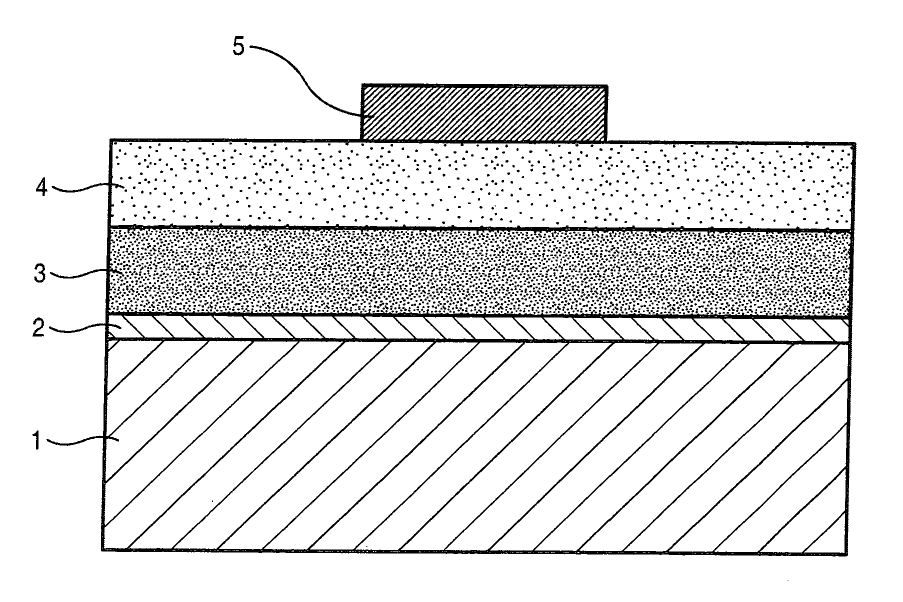
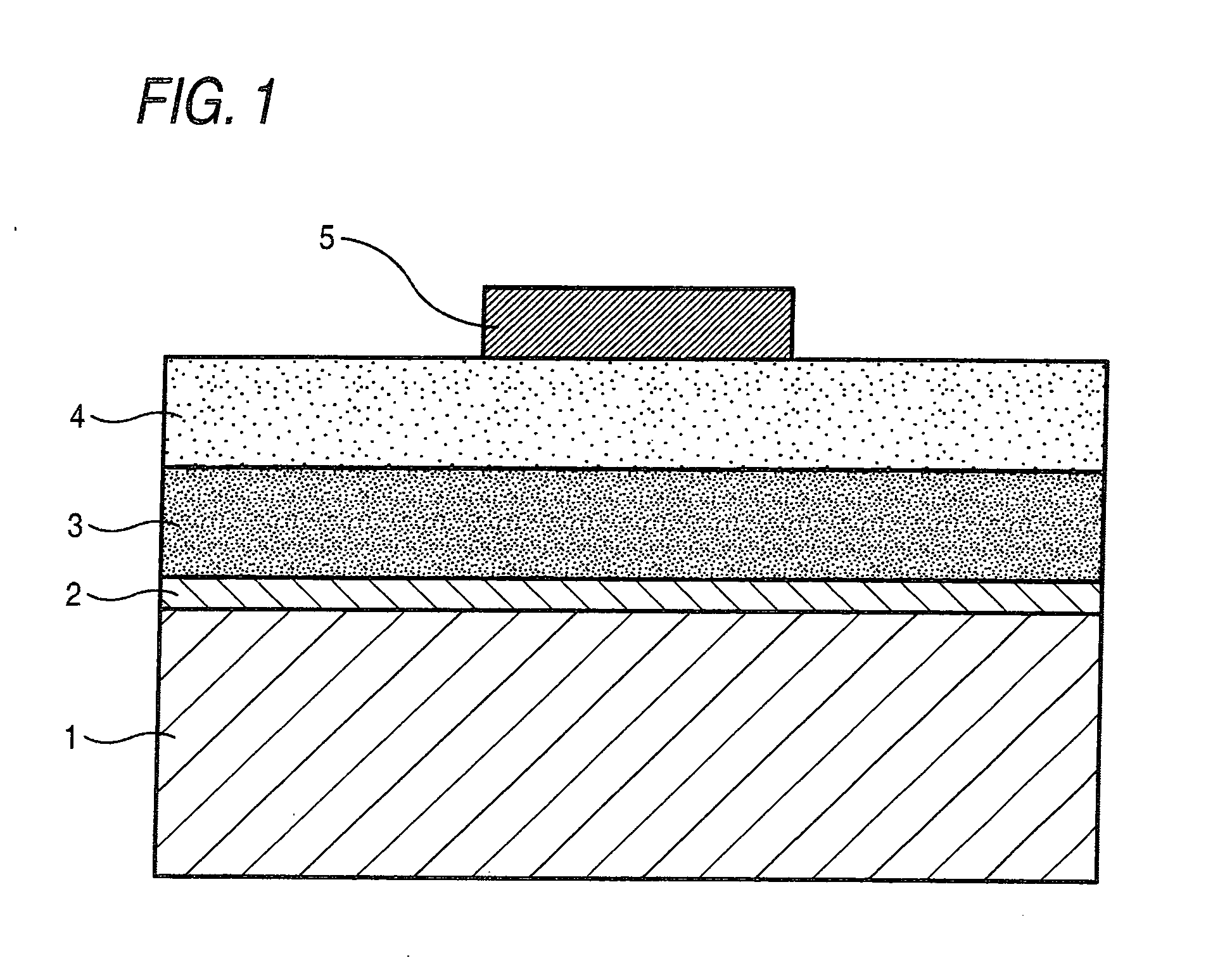
[0102]Direct-current-drive inorganic EL devices were made using the inorganic phosphor particles of Sample C prepared in Example 1 and those of each of Samples H to K prepared in Example 2, respectively. A diagrammatic sketch of the structure of each direct-current-drive inorganic EL device is shown in FIG. 1.

[0103]A first electrode (2) as a transparent electrode was provided on a transparent glass substrate 1 through formation of a 200 nm-thick ITO layer by sputtering. On the first electrode (2), the inorganic phosphor particles of each of Sample C and Samples H to K were formed into a film by means of EB evaporation apparatus. More specifically, the inorganic phosphor particles of each sample were placed as a first evaporation source, and metallic selenium as a second evaporation source. The inorganic phosphor particles were evaporated at a constant film-formation rate from the first evaporation source and, in the first half of film formation, the metallic selenium was evaporated ...


PUM


Abstract

Inorganic phosphor particles are provided, each of which containing: a matrix including at least one compound selected from the group consisting of II Group-XVI Group compounds, XII Group-XVI Group compounds, and mixed crystals thereof; and at least one metal element selected from the group consisting of metal elements belonging to Groups 6 to 11 in second transition series and third transition series of the periodic table, the metal element forming a luminescent center including wherein at least 30% of all the inorganic phosphor particles are particles each having at least 10 stacking fault planes at intervals of at most 5 nm.

Description

TECHNICAL FIELD[0001]The present invention relates to inorganic phosphor particles useful for an alternating-current dispersed inorganic electroluminescent device, an alternating-current thin-film inorganic electroluminescent device, a direct-current thin-film inorganic electroluminescent device and the like.BACKGROUND ART[0002]Phosphors are materials that emit light when energy, such as light, electricity, pressure, heat or electron beams, is applied thereto externally, and they are materials having been known for a long time. Of such materials, the phosphors made up of inorganic materials have been used in Braun tubes, fluorescent lamps, electroluminescent (EL) devices and the like from their photoemission characteristics and stability. In recent years, research has been actively done on inorganic phosphors for uses as color conversion materials in LEDs and those for excitation by slow electron beams as in PDPs.[0003]Electroluminescent (EL) devices using inorganic phosphors are ro...

Claims


Application Information

Patent Timeline
IPC IPC(8): C09K11/87C09K11/08
CPCC09K11/873H05B33/14C09K11/876C09K11/87
Inventor SHIRATA, MASASHI
Owner FUJIFILM CORP
Why Eureka
Try Eureka