Variable valve actuation apparatus of internal combustion engine

a valve actuation and internal combustion engine technology, applied in mechanical equipment, engines, machines/engines, etc., can solve the problems of insufficient engine torque response, undesirable interference between engine valve and piston head, and difficulty in sufficiently improving fuel economy during operation, etc., to achieve the effect of improving control responsiveness

Inactive Publication Date: 2009-07-30
HITACHI LTD
View PDF2 Cites 14 Cited by
  • Summary
  • Abstract
  • Description
  • Claims
  • Application Information

AI Technical Summary

Benefits of technology

[0006]It is, therefore, in view of the previously-described disadvantages of the prior art, an object of the invention to provide a variable valve actuation apparatus of an internal combustion engine, which is configured to reconcile both a satisfactory phase-advance of intake valve open timing IVO during a middle working-angle control mode and an improved control responsiveness during a transition between different working-angle control modes.

Problems solved by technology

As a result of this, it is difficult to sufficiently improve fuel economy during such a middle working-angle control mode.
However, under these conditions (i.e., with intake valve open timing IVO remarkably phase-advanced by virtue of the VTC system at the middle working-angle control mode achieved by the VEL system), when a transition to a large working-angle control mode occurs due to a requirement for a rapid vehicle acceleration, there is a risk of undesirable interference between the engine valve and the piston head and / or insufficient engine torque response, owing to a response delay of the VTC system.

Method used


Image

  • Variable valve actuation apparatus of internal combustion engine
  • Variable valve actuation apparatus of internal combustion engine
  • Variable valve actuation apparatus of internal combustion engine

Examples


first embodiment

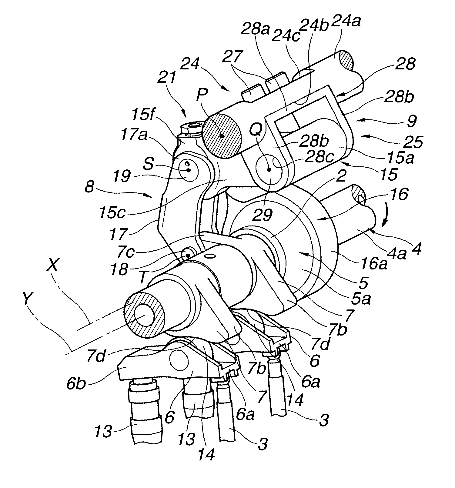
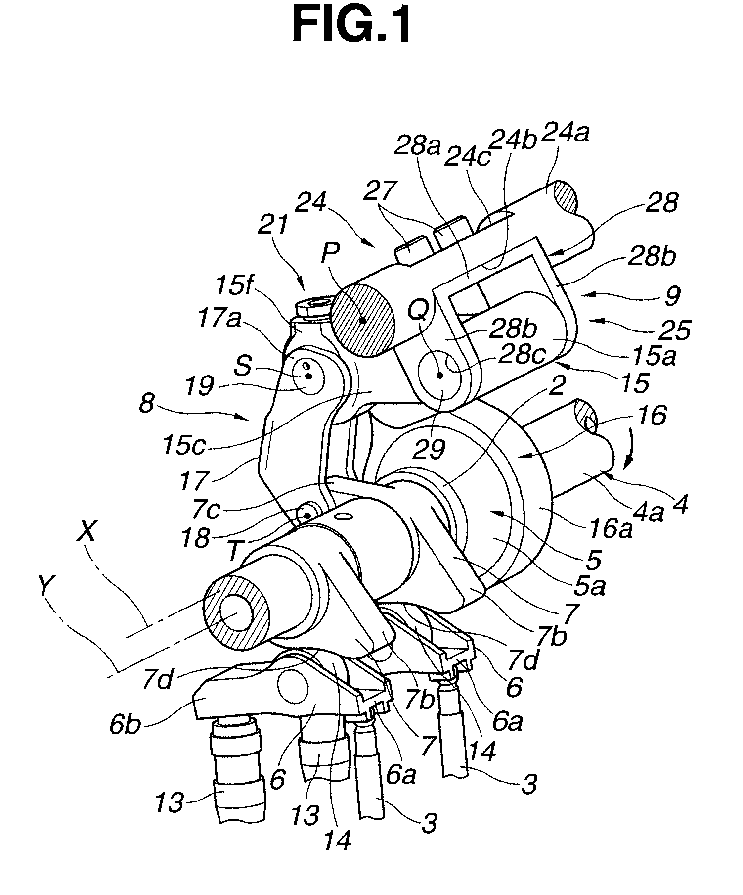
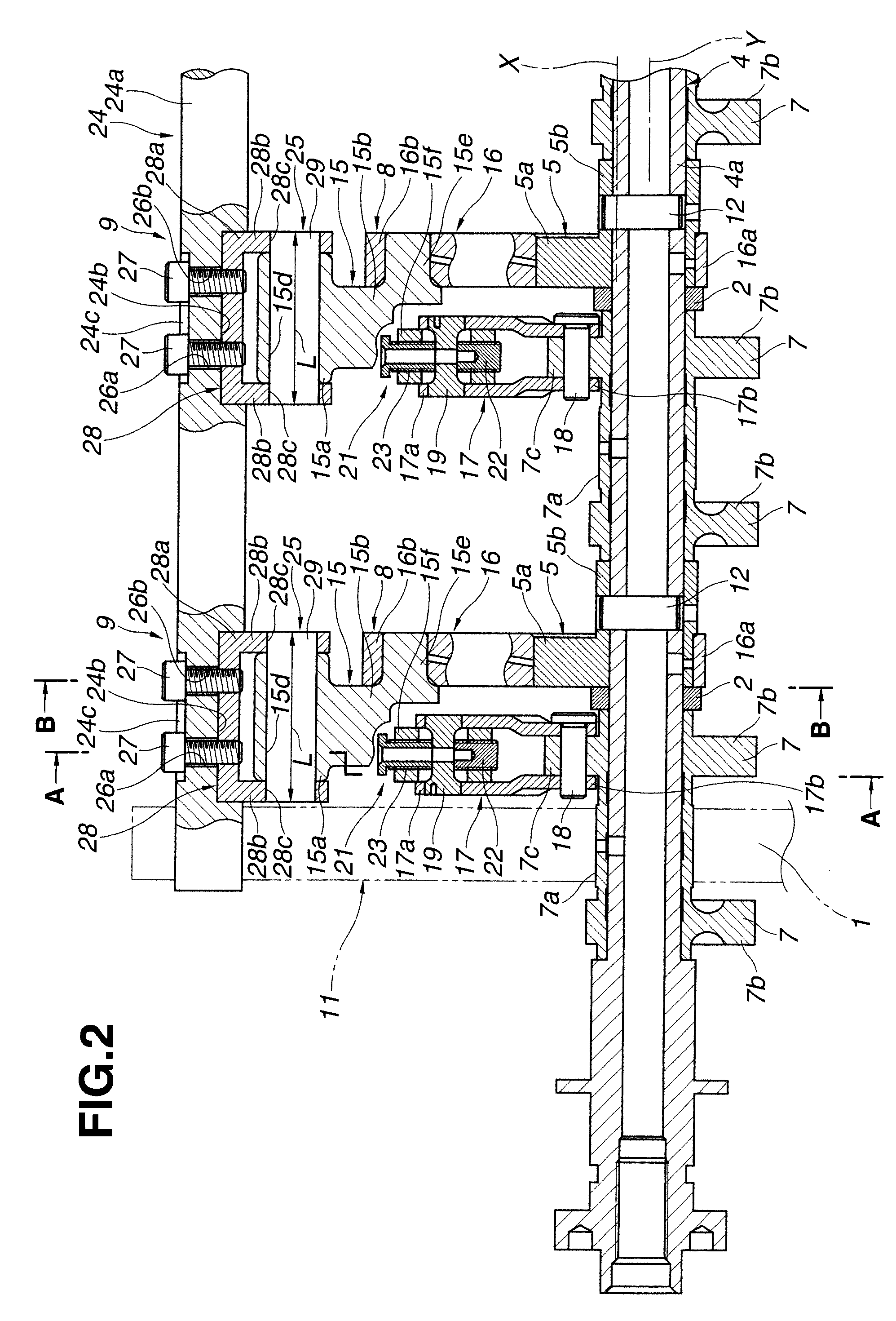
[0029]Referring now to the drawings, particularly to FIGS. 1-2, the variable valve actuation apparatus of the first embodiment is exemplified in an internal combustion engine having four valves for each cylinder, namely, two intake valves and two exhaust valves per one cylinder. In the first embodiment shown in FIGS. 1-2, the variable valve actuation apparatus of the first embodiment is applied to only the intake-valve side.

[0030]As shown in FIGS. 1-2, the variable valve actuation apparatus of the first embodiment is comprised of a cylindrical-hollow drive shaft 4 arranged to extend in a longitudinal direction of the engine, a pair of rockable cams 7, 7 provided for actuating respective intake valves 3, 3 via a pair of swing arms 6, 6, each of which serves as a roller follower resting on the tip of the valve stem of the associated intake valve 3, a motion transmission mechanism 8 (simply, a motion converter), which mechanically links a drive eccentric cam 5, fixedly connected to dri...

second embodiment

[0107]Referring now to FIGS. 12 and 13A-13B, there is shown the detailed structure of the multinodular-link motion mechanism of the variable valve actuation apparatus of the second embodiment. The fundamental structure of the apparatus of the second embodiment of FIGS. 12 and 13A-13B is similar to the first embodiment of FIGS. 1-3, except that, in the second embodiment, the structure of first arm portion 15b of rocker arm 15 is altered. Thus, the same reference signs used to designate elements in the first embodiment shown in FIGS. 1-3 will be applied to the corresponding elements used in the second embodiment shown in FIGS. 12 and 13A-13B, for the purpose of comparison of the first and second embodiments.

[0108]As seen in FIG. 13A, the tip of first arm portion 15b is formed into a two-pronged shape, namely, two parallel pronged portions 15b, 15b. Two bores 15g, 15g are formed in respective pronged portions 15b, 15b, in such a manner as to laterally penetrate the sidewalls of pronged...

third embodiment

[0111]Referring now to FIGS. 14-15, there is shown the detailed structure of the multinodular-link motion mechanism of the variable valve actuation apparatus of the third embodiment. The fundamental structure of the apparatus of the third embodiment of FIGS. 14-15 is similar to the second embodiment of FIGS. 12 and 13A-13B, except that, in the third embodiment, drive eccentric cam 5 is arranged between the rockable-cam pair 7, 7 and additionally multinodular-link motion transmission mechanism 8 has a pair of link rods 17, 17 per cylinder.

[0112]Concretely, as shown in FIG. 14, control support shaft 24a is formed with comparatively long flat recessed portions 24b, 24b, . . . , at its axial positions corresponding to respective rocker arms 15, 15, . . . . For the sake of simplicity, only one flat recessed portion 24b, associated with rocker arm 15 for only one cylinder, is shown. Bracket 28 is secured and fixedly connected onto the bottom flat face of flat recessed portion 24b by screw...


PUM


Abstract

A variable valve actuation apparatus of an internal combustion engine has a multinodular-link motion converter, to vary at least a working angle. A position of rotation of a control shaft, variably adjusting the attitude of the motion converter, is set, so that, at a peak lift during a valve opening period, an angle γ2 between an extension line of a line segment connecting a first fulcrum corresponding to a drive-eccentric-cam center and a second fulcrum provided on a rocker arm and a line segment connecting the second fulcrum and a third fulcrum provided on the rocker arm at a position different from the second fulcrum at a middle working-angle control mode is less than both an angle γ1 between the two line segments at a minimum working-angle control mode and an angle γ3 between the two line segments at a maximum working-angle control mode.

Description

TECHNICAL FIELD[0001]The present invention relates to a variable valve actuation apparatus of an internal combustion engine, capable of varying at least a working angle of an engine valve.BACKGROUND ART[0002]As is generally known, in recent years there have been proposed and developed various variable valve actuation devices, in which a working angle of an engine valve (an intake valve and / or an exhaust valve) can be variably controlled depending on an engine operating condition, in order to ensure improved fuel economy and stable driveability (improved operational stability of the engine or stable engine speeds) during low-speed and low-load operation and also to ensure a sufficient engine power output caused by an enhanced intake-air charging efficiency during high-speed and high-load operation. One such variable valve actuation device has been disclosed in Japanese Patent Provisional Publication No. 11-264307 (hereinafter is referred to as “JP11-264307”), corresponding to U.S. Pa...

Claims


Application Information

Patent Timeline
Patent Type & Authority Applications(United States)
IPC IPC(8): F01L1/34
CPCF01L13/0026Y10T74/2107F01L2820/032F01L2013/0073
Inventor NAKAMURA, MAKOTOHOSAKA, NORIMOIKAJIURA, MIKIHIROYAMADA, YOSHIHIKOTSURUTA, SEIJIHARA, SEINOSUKE
Owner HITACHI LTD
Why Eureka
Try Eureka