Methods of detecting, preventing, and remediating lost circulation

a technology of circulation loss and detection method, applied in the field of lost circulation, can solve the problems of substantial amount, virtually all of the fluid in the wellbore may be lost to the formation, and the circulation loss is reduced, and achieves the effect of reducing the loss of fluid

Active Publication Date: 2009-07-30
MI
View PDF2 Cites 62 Cited by
  • Summary
  • Abstract
  • Description
  • Claims
  • Application Information

AI Technical Summary

Benefits of technology

[0012]In one aspect, embodiments disclosed herein relate to a method for planning a wellbore, the method including defining drilling data for drilling a segment of a planned wellbore and identifying a risk zone in the segment. Additionally, the method including determining an expected fluid loss for the risk zone and selecting a solution to reduce fluid loss in the risk zone.

Problems solved by technology

Frequently, undesirable formation conditions are encountered in which substantial amounts or, in some cases, practically all of the wellbore fluid may be lost to the formation.
Lost circulation is a recurring drilling problem, characterized by loss of drilling mud into downhole formations.
Other problems encountered while drilling and producing oil and gas include stuck pipe, hole collapse, loss of well control, and loss of or decreased production.
Lost circulation may also result from induced pressure during drilling.
Specifically, induced mud losses may occur when the mud weight, required for well control and to maintain a stable wellbore, exceeds the fracture resistance of the formations.
A particularly challenging situation arises in depleted reservoirs, in which the drop in pore pressure weakens hydrocarbon-bearing rocks, but neighboring or inter-bedded low permeability rocks, such as shales, maintain their pore pressure.
This can make the drilling of certain depleted zones impossible because the mud weight required to support the shale exceeds the fracture resistance of the sands and silts.
The problem associated with producing from a well in this manner relates to the control of the flow of fluids from the well and to the management of the reservoir.
The production of water near the heel reduces the overall production from the well.

Method used


Image

  • Methods of detecting, preventing, and remediating lost circulation
  • Methods of detecting, preventing, and remediating lost circulation
  • Methods of detecting, preventing, and remediating lost circulation

Examples


Embodiment Construction

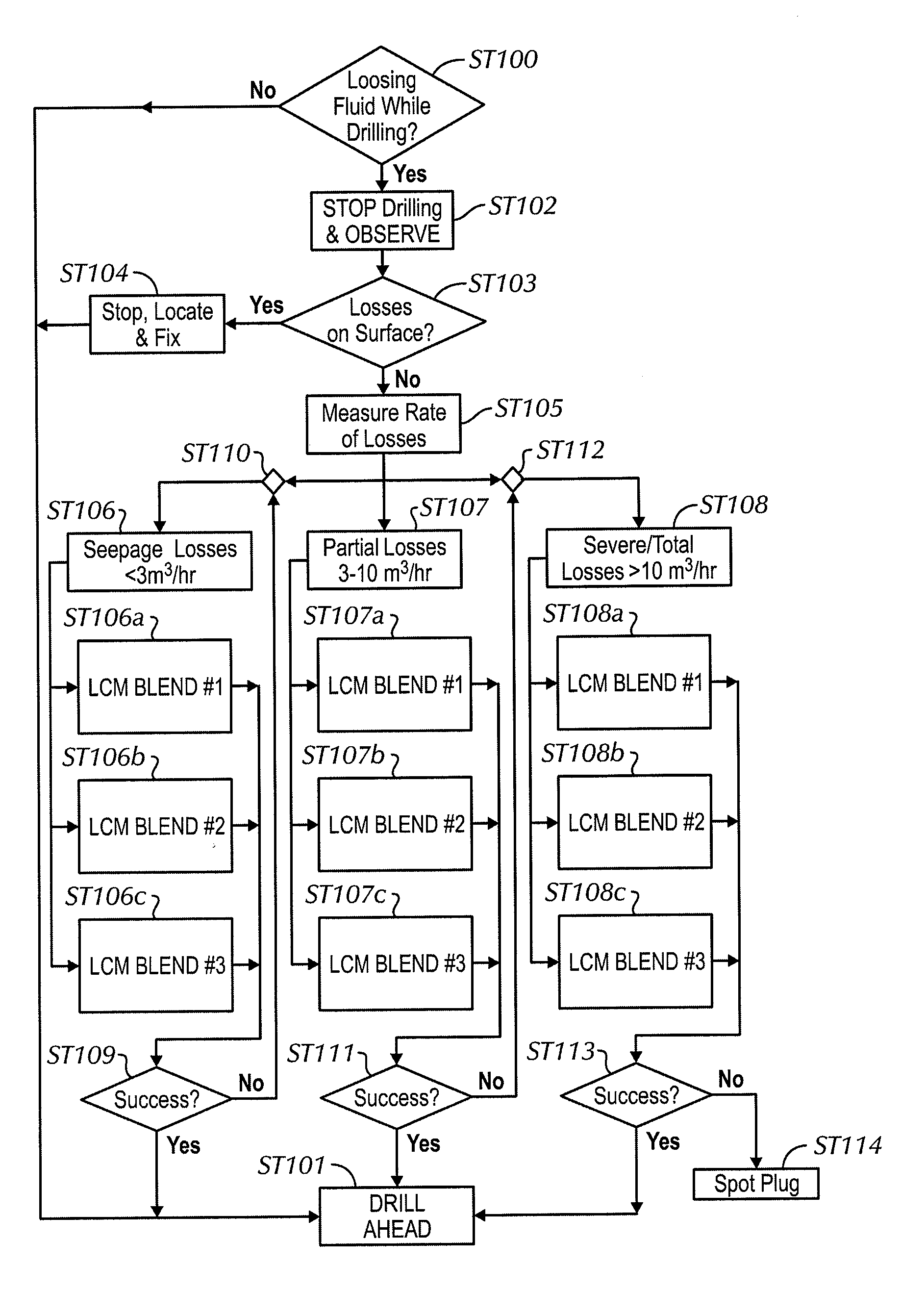
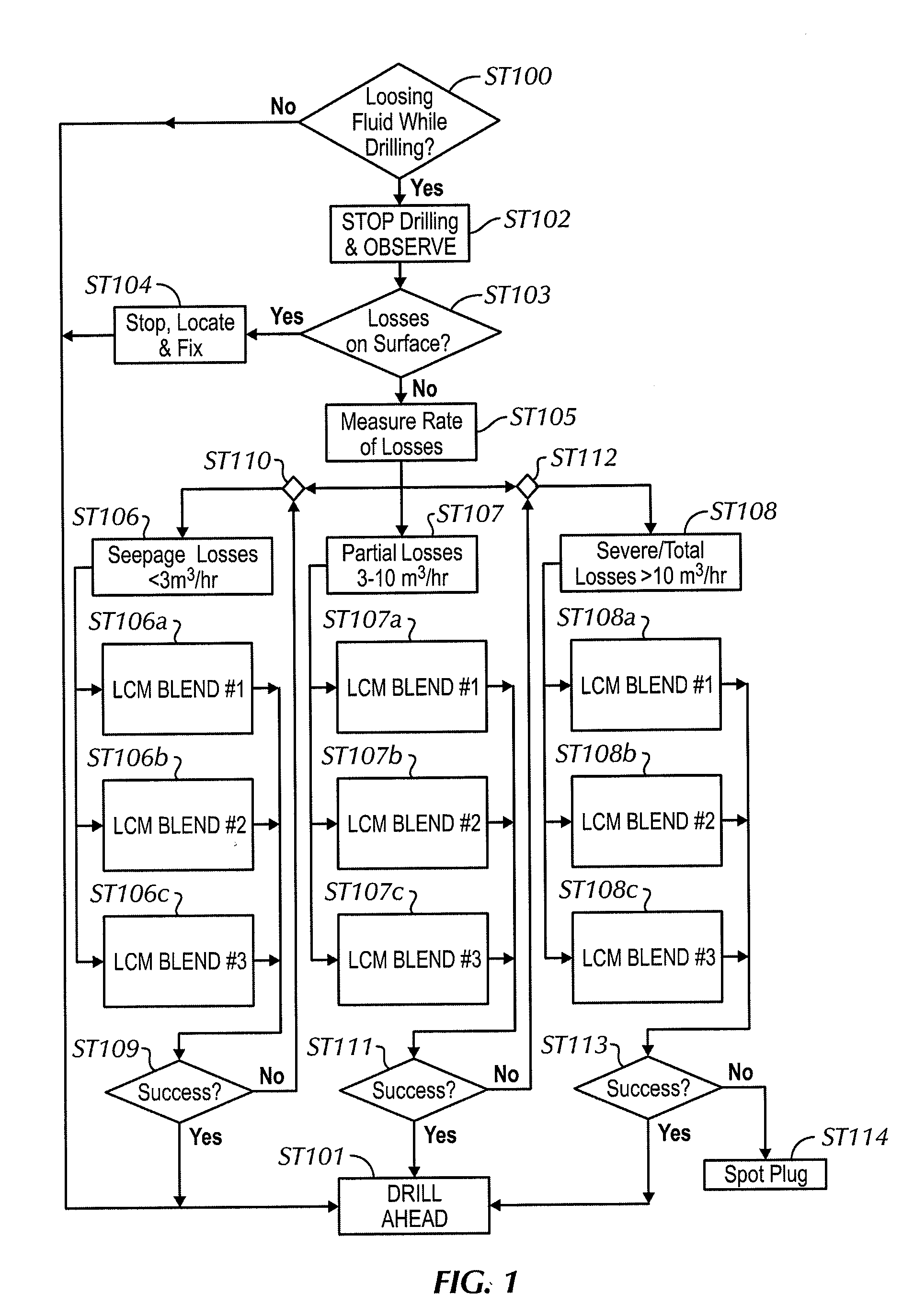
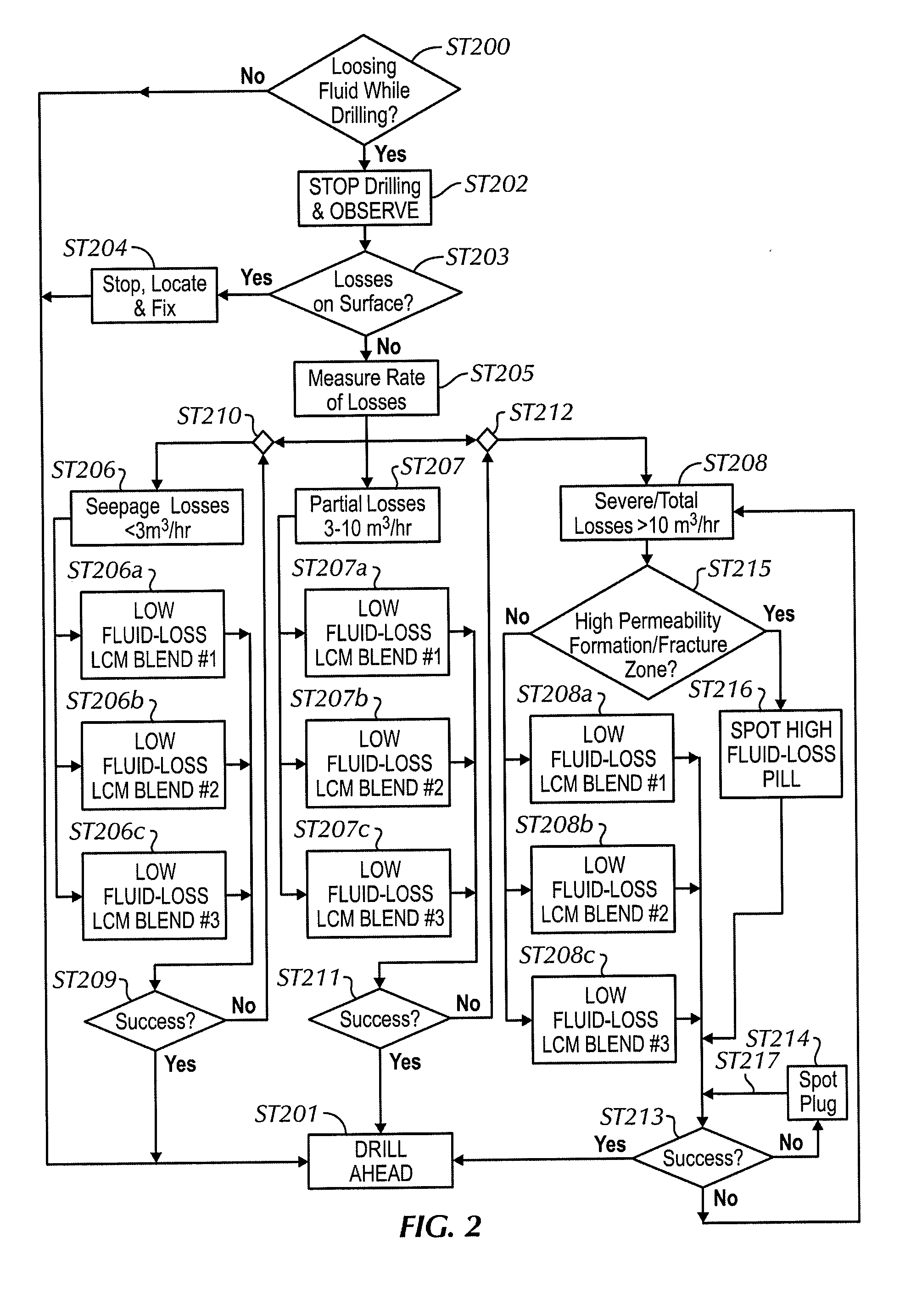
[0020]In one aspect, embodiments disclosed herein relate generally to lost circulation experienced during drilling of a wellbore. In specific aspects, embodiments disclosed herein relate to the detection, classification, and remedial treatment of lost circulation occurrences. In other specific aspects, embodiments disclosed herein also relate to the anticipation of lost circulation during wellbore planning and preventative treatments to minimize the occurrences of such lost circulation.

[0021]Cause and Location of Loss

[0022]As described above, lost circulation may be naturally occurring, the result of drilling through various formations such as unconsolidated formations having high permeability, naturally fractured formations including limestone, chalk, quartzite, and brittle shale, vugular or cavernous zones, etc. Appreciation of such types of formation that may be expected in planning a wellbore (or at least segments thereof) and / or encountered during drilling through particular se...


PUM


Abstract

A method for planning a wellbore, the method including defining drilling data for drilling a segment of a planned wellbore and identifying a risk zone in the segment. Additionally, the method including determining an expected fluid loss for the risk zone and selecting a solution to reduce fluid loss in the risk zone. Furthermore, a method for treating drilling fluid loss at a drilling location, the method including calculating a drilling fluid loss rate at the drilling location, classifying the drilling fluid loss based on the drilling fluid loss rate, and selecting a solution based at least in part on the classifying.

Description

CROSS-REFERENCE TO RELATED APPLICATION(S)[0001]This application claims priority, pursuant to 35 U.S.C. § 119(e), of U.S. Provisional Application Ser. No. 61 / 024,807, filed on Jan. 30, 2008, and is hereby incorporated by reference.BACKGROUND OF INVENTION[0002]1. Field of the Invention[0003]Embodiments disclosed herein relate generally to lost circulation experienced during drilling a wellbore. In particular, embodiments disclosed herein relate to the detection, classification, and remedial treatment of lost circulation occurrences. Additionally, embodiments disclosed herein also relate to the anticipation of lost circulation during wellbore planning and preventative treatments to minimize the occurrences of such lost circulation.[0004]2. Background Art[0005]During the drilling of a wellbore, various fluids are typically used in the well for a variety of functions. The fluids may be circulated through a drill pipe and drill bit into the wellbore, and then may subsequently flow upward ...

Claims


Application Information

Patent Timeline
Patent Type & Authority Applications(United States)
IPC IPC(8): E21B47/00E21B7/00
CPCE21B21/003E21B7/00E21B47/00
Inventor KAAGESON-LOE, NILSDAATLAND, TRONDRANDEBERG, OYSTEINASKO, ARNEGROWCOCK, FREDERICK B.MANESCU, GABESANDERS, MARK
Owner MI
Why Eureka
Try Eureka