Image display device and electronic apparatus

Active Publication Date: 2009-07-30
SEIKO EPSON CORP
View PDF1 Cites 10 Cited by
  • Summary
  • Abstract
  • Description
  • Claims
  • Application Information

AI Technical Summary

Benefits of technology

[0006]An advantage of some aspects of the invention is that it provides an image display device and an electronic appara

Problems solved by technology

However, there has been a problem in that PWM control of a light source causes a phenomenon (scroll noise) where band-shaped bright and dark por

Method used


Image

  • Image display device and electronic apparatus
  • Image display device and electronic apparatus
  • Image display device and electronic apparatus

Examples


Embodiment Construction

[0018]Embodiments of the invention will be described with reference to the drawings.

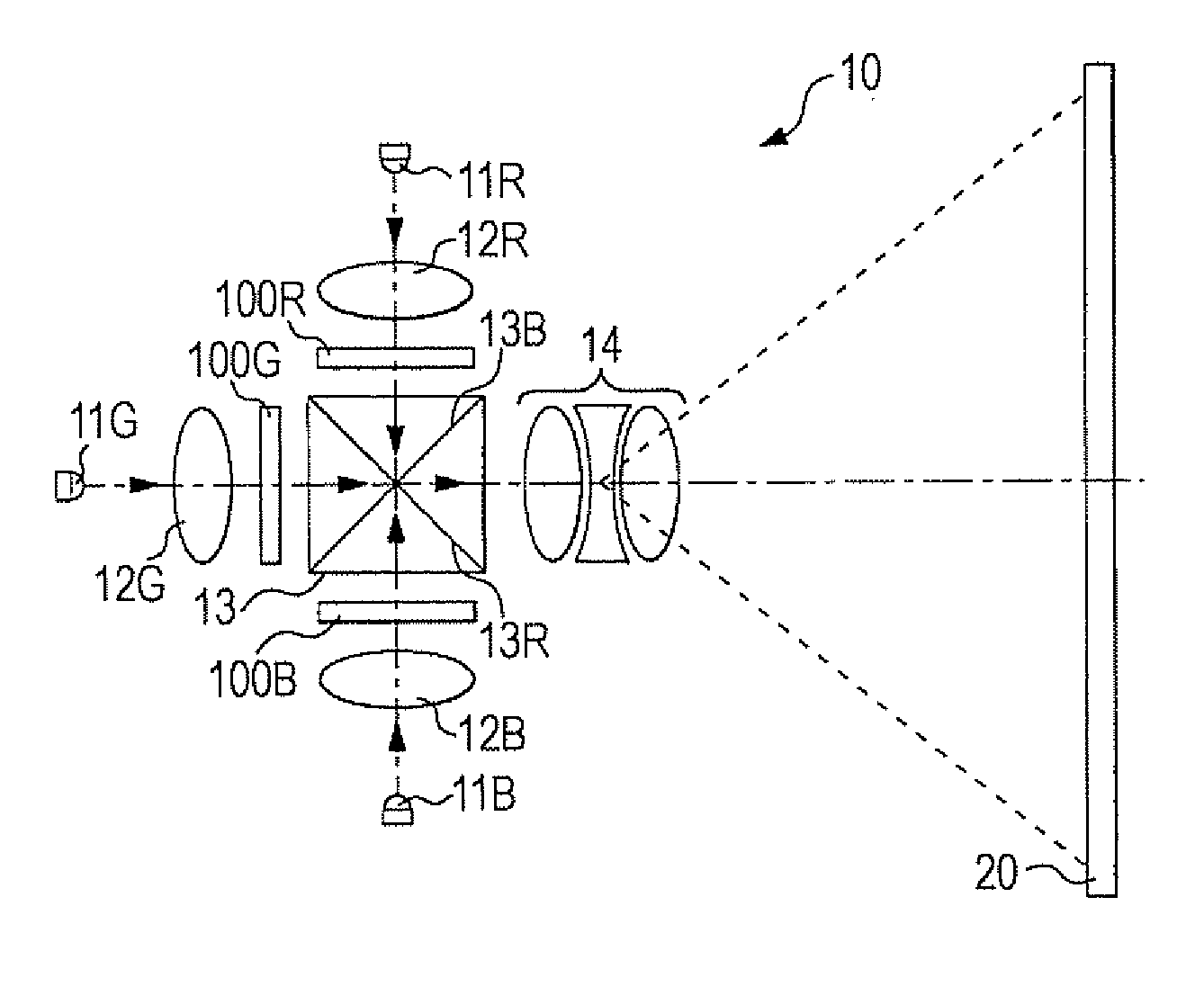
[0019]FIG. 1 is a plan view showing an optical configuration of a projector 10 to which an image display device according to an embodiment of the invention is applied.

[0020]Referring to FIG. 1, an LED 11R is an example of a solid-state light source. The LED 11R emits red (R) light and is located in the direction of twelve o'clock when viewed from the center of a dichroic prism 13. A collimator lens 12R collimates red light emitted from the LED 11R and causes the collimated red light to be incident on a display panel 100R. In this embodiment, the display panel 100R is a transmissive liquid crystal panel. The display panel 100R includes a plurality of pixels and changes the transmittance of an individual pixel. Thus, light emitted from the display panel 100R represents an image of red (R) components.

[0021]Similarly, LEDs 11G and 11B emit green (G) light and blue (B) light, respectively. Referring to FI...


PUM


Abstract

An image display device includes at least one light source that emits light; at least one display area that changes, for each pixel, a transmittance or a reflectance of the light emitted from the light source; a panel driving circuit that drives the display area on the basis of an image signal indicating the transmittance or the reflectance for each pixel; and a light source control unit that controls a proportion of a light emission time of the light source in a period that varies within a predetermined range.

Description

BACKGROUND[0001]1. Technical Field[0002]The present invention relates to a technique for reducing display unevenness in the case of controlling luminance by performing pulse width modulation (PWM) of a light source.[0003]2. Related Art[0004]The luminance of a light source, such as a laser diode (LD) or a light-emitting diode (LED), can be easily adjusted by performing PWM control. This is because PWM is excellent in terms of being established using a digital circuit and ensuring the stability of the light intensity and the circuit. Under such circumstances, a technique in which such a light source is applied to, for example, a projector, has been suggested, for example, in JP-A-2004-354717. In this technique, color changes are reduced, and a display dynamic range is apparently increased.[0005]However, there has been a problem in that PWM control of a light source causes a phenomenon (scroll noise) where band-shaped bright and dark portions extending in a horizontal direction move sl...

Claims


Application Information

Patent Timeline
IPC IPC(8): G09G3/36
CPCG09G3/3406G09G2320/064G09G2320/0233G09G3/34G09G3/02G03B21/00
Inventor TOYOOKA, TAKASHI
Owner SEIKO EPSON CORP
Why Eureka
Try Eureka