Lens having vibration proof function and imaging apparatus

Inactive Publication Date: 2009-07-30
FUJI PHOTO OPTICAL CO LTD
View PDF4 Cites 11 Cited by
  • Summary
  • Abstract
  • Description
  • Claims
  • Application Information

AI Technical Summary

Benefits of technology

[0008]An object of an illustrative, non-limiting embodiment of the invention is to provide a telephoto lens, which can attain vibration proof effects effectively with a small moving amount and can employ a vibration proof mecha

Problems solved by technology

Further, the weight of the telephoto lens increases as the focal length becomes longer and so the image vibration due to the hand movement will be caused at

Method used


Image

  • Lens having vibration proof function and imaging apparatus
  • Lens having vibration proof function and imaging apparatus
  • Lens having vibration proof function and imaging apparatus

Examples


examples

[0058]Next, concrete numeral examples in a telephoto lens according to the embodiment will be explained. Hereinafter, plural examples will be explained collectively.

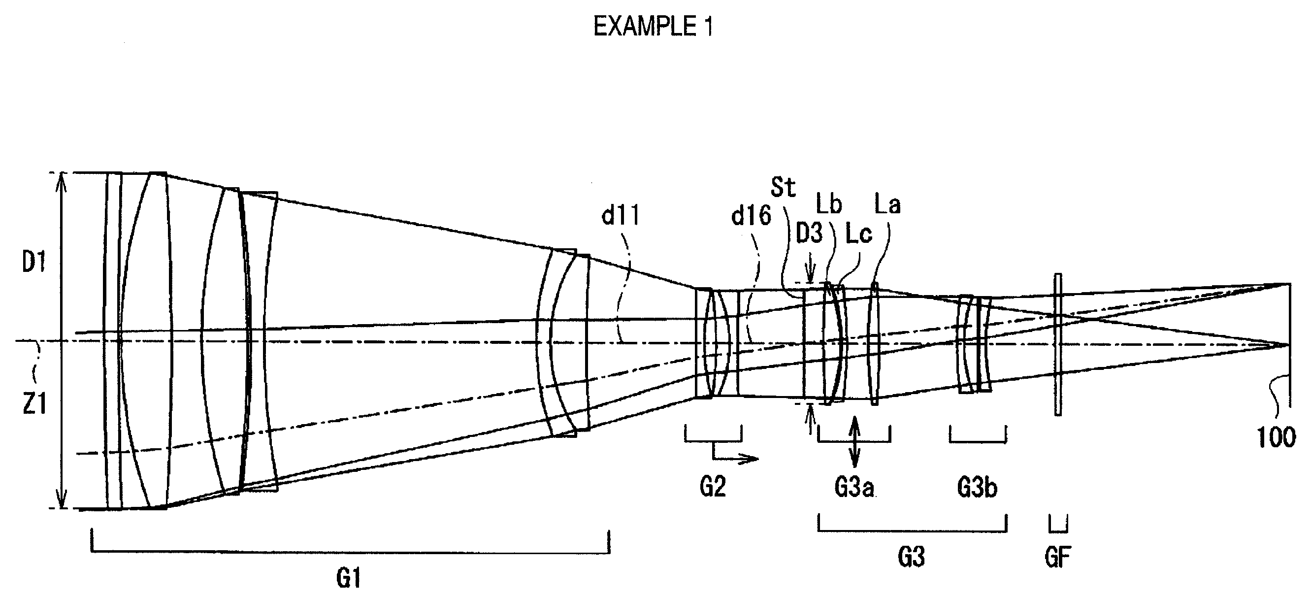
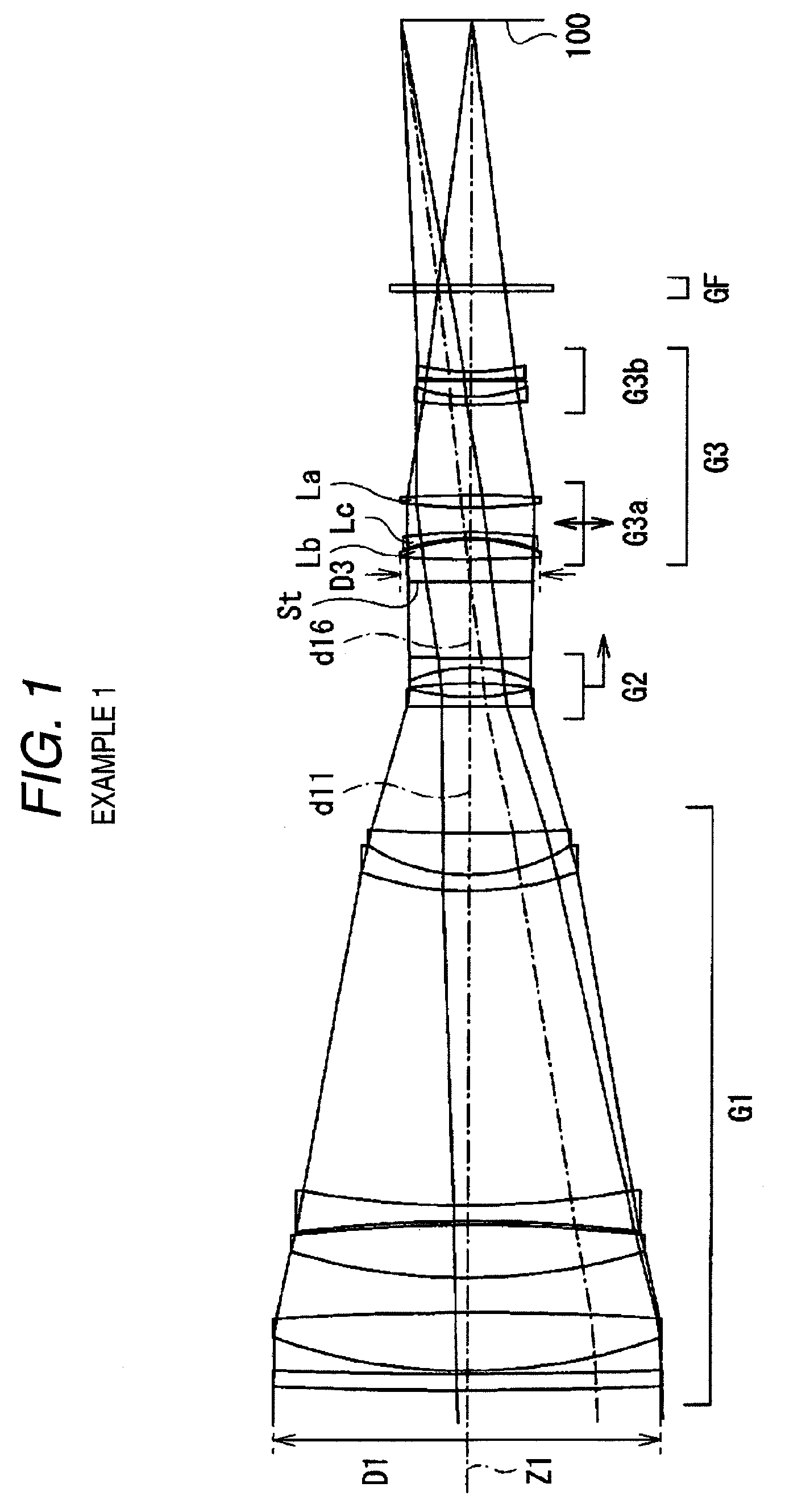
[0059]FIG. 6 shows Example 1 of concrete lens data corresponding to the configuration of the telephoto lens shown in FIG. 1. The column of a surface No. Si of the lens data shown in FIG. 6 represents i-th surface number of the telephoto lens acceding to Example 1 in a manner that the surface of the constituent element on the most object side is the first surface and the number increases sequentially toward the object side. The column of a radius of curvature Ri represents a value (mm) of the radius of curvature of the i-th surface from the object side. Similarly, the column of a surface spacing di represents a space (mm) on the optical axis between the i-th surface Si and the (i+1)-th surface Si+1 from the object side. The column of Ndj represents a value of a refractive index at the d-line (wavelength 587.6 nm) of the j...


PUM


Abstract

A telephoto lens having a vibration proof function is provided and includes: in order from an object side of the telephoto lens, a first lens group having a positive refractive power; a second lens group having a negative refractive power; and a third lens group having a positive refractive power. The second lens group is moved along an optical axis thereof to perform focusing. The third lens group includes a 3a-th group having a positive refractive power and a 3b-th group having a negative refractive power in the order from the object side. The 3a-th group is moved in a direction orthogonal to the optical axis to correct an image vibration of a taken image. The telephoto lens satisfies a specific conditional expression.

Description

[0001]This application is based on and claims priority under 35 U.S.C § 119 from Japanese Patent Application No. 2008-018093, filed on Jan. 29, 2008, the entire disclosure of which is herein incorporated by reference.BACKGROUND OF THE INVENTION[0002]1. Field of the Invention[0003]The present invention relates to a vibration proof optical system and, in particular, relates to a telephoto lens to be mounted on a film camera or an electronic camera using an imaging device such as a CCD (charge coupled device) and relates to an imaging apparatus which mounts the telephoto lens as an imaging lens system.[0004]2. Description of Related Art[0005]There is known a method in which a part of lenses within an optical system is moved in a direction orthogonal to an optical axis in order to correct the image vibration of a taken image, caused by the vibration of the optical system due to hand movement. Japanese Patent No. 3590845 discloses the invention of an image position correcting optical sys...

Claims


Application Information

Patent Timeline
IPC IPC(8): G02B13/02
CPCG02B27/646G02B13/02
Inventor SUZUKI, TAKASHI
Owner FUJI PHOTO OPTICAL CO LTD
Why Eureka
Try Eureka