Electronic fuses

a technology of electronic fuse and fuses, applied in the field of electronic fuse, can solve the problems of more likely faults in data stores, and achieve the effects of less data, less data, and convenient data acquisition

Active Publication Date: 2009-07-30
ARM LTD
View PDF15 Cites 56 Cited by
  • Summary
  • Abstract
  • Description
  • Claims
  • Application Information

AI Technical Summary

Benefits of technology

[0012]The present invention recognizes that fusebox data for repairing faulty elements in circuitry can be very large and thus, compacting the data is advantageous. Furthermore, although there may be many locations that could be faulty most of them will not be. Data of this sort lends itself well to compaction. Furthermore, expanding the compacted data within the fusebox controller itself which is remote from the fusebox results in less data being transmitted between the fusebox and fusebox controller. The ability to transmit less data provides a fast system in which less power and less time is required to repair the circuitry.
[0013]Although, such a system is useful for correcting faults in many different circuitry it is particularly helpful for correcting for faults in data stores. Data stores are being produced with ever increasing storage capacity and ever decreasing size. Restricting size in this way makes faults within the data stores more likely. Being able to correct these faults is clearly advantageous.

Problems solved by technology

Restricting size in this way makes faults within the data stores more likely.

Method used


Image

  • Electronic fuses
  • Electronic fuses
  • Electronic fuses

Examples


Embodiment Construction

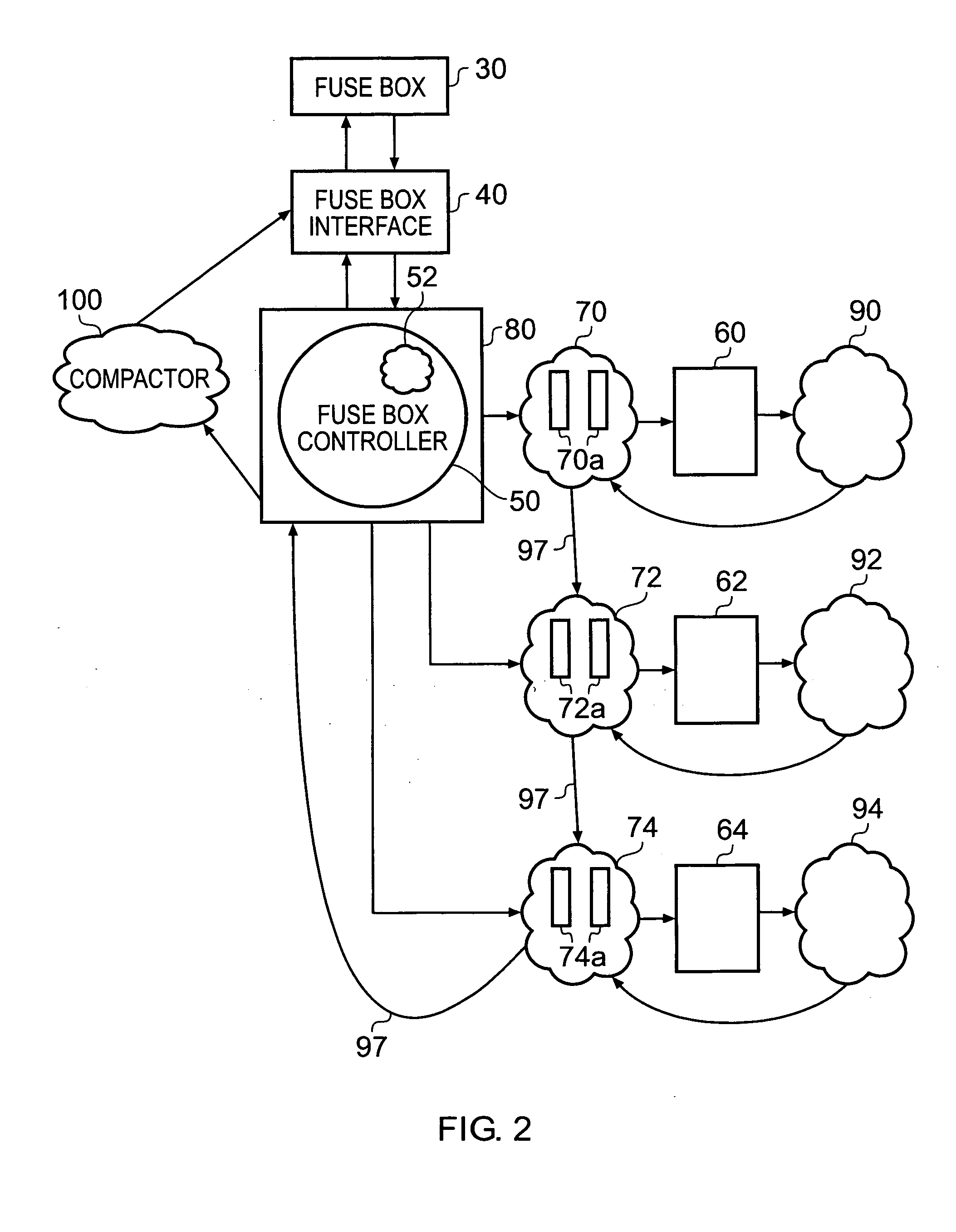
[0052]FIG. 2 shows a fusebox 30, a fusebox interface 40 and a fusebox controller 50 according to an embodiment of the present invention. Associated with fusebox controller 50 are three memories 60, 62 and 64. With each of these is associated a wrapper 70, 72 and 74. Each wrapper comprises a number of registers 70A, 72A, 74A. Fusebox controller 50 is contained within memory test controller 80. Memory test controller 80 sends out test data via wrapper 70 to fill the respective memories 60 to 64 and looks at the pattern generated using comparison logic 90 to 94. This comparison logic isolates the faults within the data store 60 to 64 and sends this information back to wrappers 70 to 74. These wrappers populate the reconfiguration registers 70a, 72a, 74a required to compensate for these faults and then perform the tests again with these reconfiguration registers loaded. If the tests are then correct they know that the reconfiguration registers had the right data and this data is shifted...


PUM


Abstract

The application discloses an integrated circuit comprising: circuitry; a fusebox for storing an array of data identifying faulty elements within said circuitry; at least one fusebox controller for repairing said faulty elements in said circuitry in response to data received from said fusebox; a data communication path linking said fusebox controller with said fusebox; wherein said data stored in said fusebox is compacted data and said at least one fusebox controller comprises a data expander for expanding said compacted data received from said fusebox via said data communication path prior to repairing any faulty elements in said circuitry.

Description

BACKGROUND OF THE INVENTION[0001]1. Field of the Invention[0002]The field of the invention relates to the repair of faulty elements within circuitry.[0003]2. Description of the Prior Art[0004]Faults within circuitry such as memories can be repaired subsequent to manufacture by the use of redundant circuit elements that can be selected by fuse programmable logic to replace the faulty elements. The redundant elements have a cost of circuit area but they do enable production yields of circuits to increase as they allow circuits with some faults to still function correctly.[0005]With the ever decreasing size of circuit elements, faults within them are becoming more likely such that the ability to be able to repair them using fuses is important.[0006]Fuses can take the form of laser programmable fuses that are programmed by vaporising material with a laser, or electrically blown fuses which are programmed by passing a high current through them.[0007]Electronic or E fuses are also known t...

Claims


Application Information

Patent Timeline
Patent Type & Authority Applications(United States)
IPC IPC(8): G11C29/04G11C7/00
CPCG11C17/18G11C29/785G11C29/027
Inventor KHOJA, FAISAL RAMZAN ALIWAGGONER, GARY ROBERTLANDINI, SAUROCHANDRAMOULI, RAMAMURTI
Owner ARM LTD
Why Eureka
Try Eureka