Sunlight attenuation visor

a technology of attenuating light and visor, which is applied in the direction of lighting and heating equipment, instruments, transportation and packaging, etc., can solve the blinding effect of sunlight through the windshield and windows of vehicles, the ineffective tinted layer only on the top portion of the windshield, and the inability to reduce the glare through the rest of the windshield

Inactive Publication Date: 2011-12-27
YANG YONGWU
View PDF6 Cites 8 Cited by
  • Summary
  • Abstract
  • Description
  • Claims
  • Application Information

AI Technical Summary

Benefits of technology

[0018]In yet another embodiment of the sunlight attenuation apparatus, the visor further comprises an opaque member and a light filtering portion comprising a frame having a pivoting edge and connected to and for supporting the first and second polarizers and the nematic liquid crystals. The visor also has a shaft connected on a pivoting edge of the frame, and two connecting portions on the pivoting edge of the frame for connecting the shaft to the opaque member. The light filtering portion can be folded onto the opaque member so that the visor can function as a traditional visor or be unfolded to automatically adjust the amount of light filtered through the apparatus.
[0019]In still another embodiment of the sunlight attenuation apparatus, the visor further comprises a jaw and spring clip assembly for connecting the visor to a traditional visor on a lower edge of the traditional visor. The visor may also include friction generating means for permitting selective positioning of the visor when the visor is rotated out of a folded position, and a spring clip for removably securing the visor to an upper edge of the traditional visor. When the visor is in a folded position, the spring clip will removably hold the visor to the traditional visor in the folded position.
[0027]When a voltage is applied across the electrodes, a torque acts to align the liquid crystal molecules parallel to the electric field. This reduces the rotation of the polarization of the incident light after the first polarizer, thus less light transmits through the second polarizer. If the applied voltage is large enough, the liquid crystal molecules are completely untwisted and the polarization of the incident light is not rotated as it passes through the liquid crystal layer. The light passed through the first polarizer is then completely absorbed by the second polarizer and thus no light goes through this device, i.e., 0% transmittance. By controlling the voltage applied across the liquid crystal layer, light passing through this device can be changed from 50% to 0%.
[0030]A further important aspect of the preferred embodiment of the present invention is to use proper filter glass to filter out the unwanted or harmful radiation from the Sun to protect a driver from long time exposure to such radiation. Solar radiation reaching the surface of the earth expands from ultraviolet (UV) radiation (wavelengths>290 nm) to radio waves (wavelength in the meter range). UV radiation (from 290 nm to 380 nm) is harmful to living organisms and near infrared light (from 700 nm to 1400 nm) cannot be seen and may contribute unwanted heating. Only visible radiation from 380 nm to 700 nm provides illumination for viewing. Therefore, using filter glass which only passes visible light from 380 nm to 700 nm for sandwiching liquid crystal layer for the device will further save the driver from exposure to such harmful and useless radiation.

Problems solved by technology

A problem that often arises for drivers of vehicles is the blinding effect of sunlight through the windshield and windows of their vehicles.
However, a tinted layer coated only on the top portion of the windshield is not effective for reducing the glare through the rest of the windshield.
Neither device reduces sunlight in the middle portion (i.e., driver's field of view) of the windshield, which sometimes can result in significant hazardous driving conditions.
Hazardous driving conditions can become even more severe during times of high traffic for those who drive east in the morning and west in the afternoon, when the sun shines directly into drivers' eyes from a low angle above the horizon.
As neither visor nor tinted layer in current vehicles reduces the direct sunlight in the middle portion of the windshield, drivers can feel a strong sting from the sun's glare.
Current state of the art general use sunglasses are not designed for looking at the sun directly.
In addition, it is inconvenient for drivers wearing prescription glasses to wear sunglasses.
Drivers may try to look slightly sideways or sit up tall and look downward to alleviate the problem, although this is inadequate as the sun's glare is prevalent throughout the field of view.
As the clarity of the front view is greatly reduced, drivers usually have to slow down dramatically, compounding the east bound traffic in the morning and west bound traffic in the evening.
This results in wasted energy resources and driver's time, and can contribute to green gas generation and thus global warming.
Both patents only teach installing a sun glare-reducing glass, and do not address the glare screen itself.
However, due to its transmission invariability, Kempt's glasses either insufficiently reduce or reduce too much sunlight depending on the materials the glasses are composed of.

Method used


Image

  • Sunlight attenuation visor
  • Sunlight attenuation visor
  • Sunlight attenuation visor

Examples


Embodiment Construction

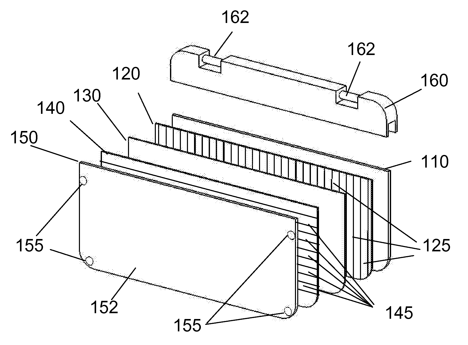
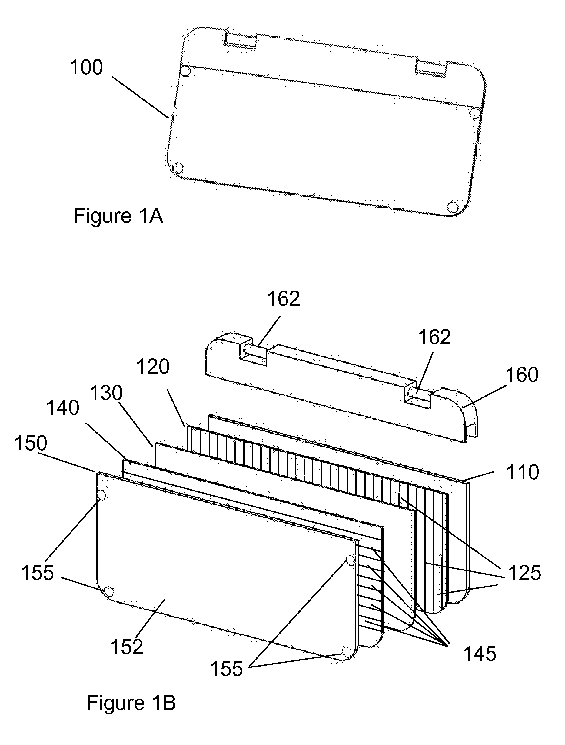
[0006]According to one embodiment of the invention, an apparatus for adjusting the intensity of light transmitted through the apparatus is provided. The apparatus comprises a first polarizer having a polarizing orientation, and a second polarizer having a polarizing orientation perpendicular to the polarizing orientation of the first polarizer. Two electrodes, a first and second electrode, are disposed between the polarizers, and a nematic liquid crystal layer is disposed between the electrodes. At least one light detector is positioned for measuring the intensity of the transmitted light, and a voltage controller is in electrical communication with the light detector. The voltage controller controls the voltage level applied to the electrodes based on the intensity of the measured light, wherein the voltage determines the amount of light transmitted through the apparatus.

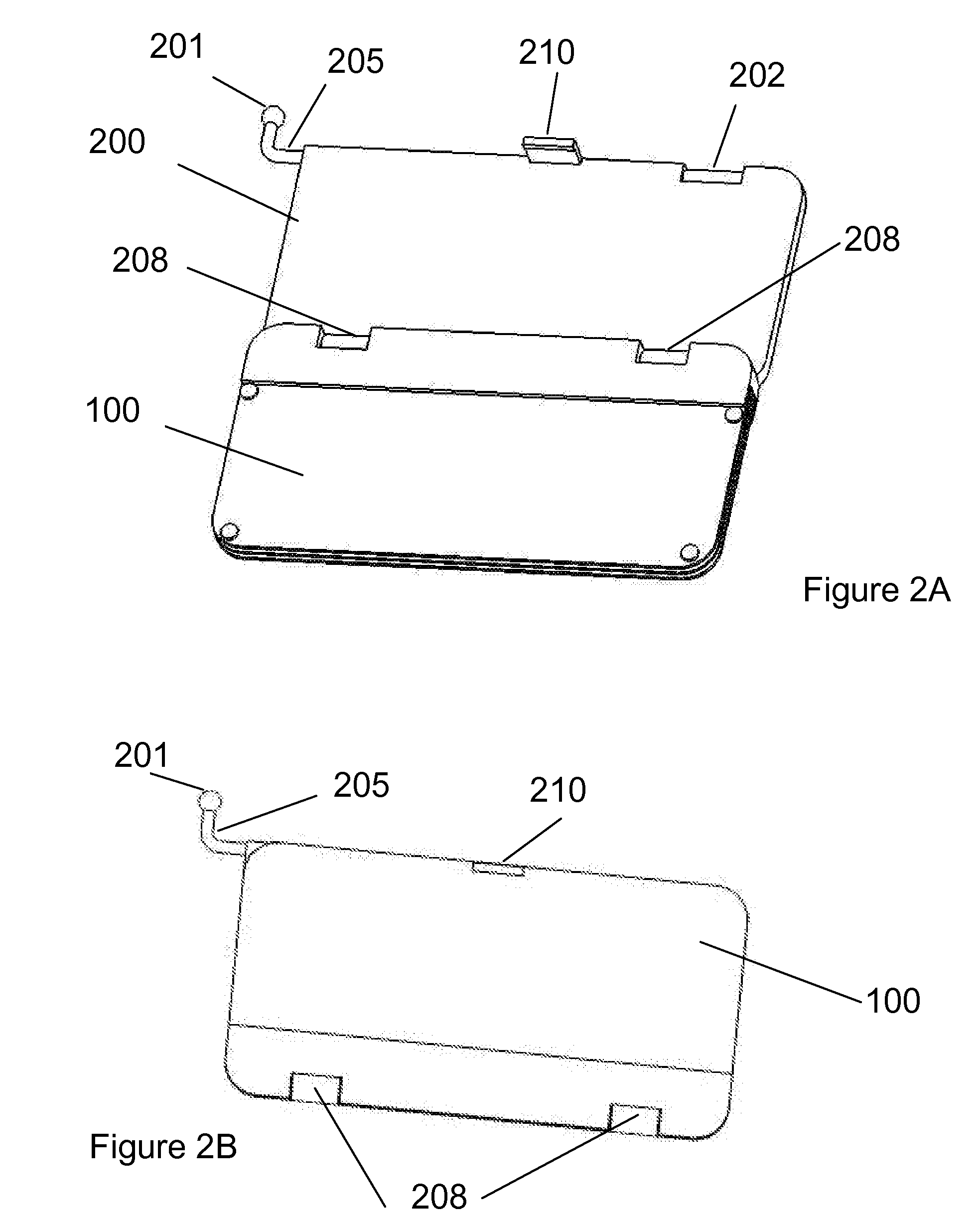
[0007]In another embodiment, the apparatus for attenuating sunlight has electrodes that are embedded on a transl...


PUM

PropertyMeasurementUnit
transmittanceaaaaaaaaaa
total transmittanceaaaaaaaaaa

Abstract

An apparatus for attenuating the intensity of light transmitted through the apparatus is provided. In one embodiment, the apparatus may comprise a first polarizer having a first polarizing orientation and a second polarizer having a polarizing orientation perpendicular to the first polarizer. First and second electrodes are disposed between the polarizers and a nematic liquid crystal layer is disposed between the electrodes. At least one light detector positioned for measuring the intensity of the transmitted light may be positioned on an outer side of the second polarizer. A voltage controller in electrical communication with the light detector is provided for controlling the voltage level applied to the electrodes based on the intensity of the measured light wherein the voltage determines the amount of light transmitted through the apparatus.

Description

TECHNICAL FIELD[0001]The present invention relates to an adjustable light attenuation apparatus, and more particularly, some embodiments relate to an automatic light attenuation apparatus adapted for use in automobiles to protect drivers from strong sunlight glare.BACKGROUND OF THE INVENTION[0002]A problem that often arises for drivers of vehicles is the blinding effect of sunlight through the windshield and windows of their vehicles. The visors positioned near the top of the windshield have been utilized as one solution to the problem of blinding sunlight. Another method of reducing sunlight glare is the use of a tinted belt-filter layer along the top portion of the windshield. However, a tinted layer coated only on the top portion of the windshield is not effective for reducing the glare through the rest of the windshield. Also, the sunlight entering through the top portion of the windshield can be blocked entirely by the blind visor. Neither device reduces sunlight in the middle ...

Claims


Application Information

Patent Timeline
Patent Type & Authority Patents(United States)
IPC IPC(8): B60Q1/00F21V1/00F21V17/02G02F1/1335
CPCG02F1/1313G02F1/13318
Inventor YANG, YONGWU
Owner YANG YONGWU
Why Eureka
Try Eureka