Vibration transducer

a technology of vibration transducer and diaphragm, which is applied in the direction of semiconductor electrostatic transducer, loudspeaker diaphragm shape, microphone structural association, etc., can solve the problems of difficult adhesion of the fixed end of the diaphragm to the substrate, and achieves increased rigidity of the diaphragm, increased acoustic resistance, and high acoustic resistance.

Inactive Publication Date: 2009-07-30
YAMAHA CORP
View PDF3 Cites 23 Cited by
  • Summary
  • Abstract
  • Description
  • Claims
  • Application Information

AI Technical Summary

Benefits of technology

[0023]In the above, a relatively high acoustic resistance should be formed between the diaphragm and the substrate in proximity to the surrounding area of the opening of the back cavity. The vibration transducer is designed such that an acoustic resistance is formed between the diaphragm and the surrounding area of the opening of the substrate, while no hole is formed in the arms in the regions positioned in proximity the opening; thus, it is possible to increase the acoustic resistance in the gap between the arms of the diaphragm and the substrate. In other words, it is possible to increase the rigidity of the diaphragm without reducing the acoustic resistance in the gap between the diaphragm and the substrate in proximity to the surrounding area of the opening of the back cavity.
[0024]When the holes are aligned in the arms of the diaphragm along multiple lines in the circumferential direction of the diaphragm, stripe-shaped irregularities may occur in the distribution of rigidity of the arms of the diaphragm, wherein stripe-shaped regions having high rigidity and other stripe-shaped regions having low rigidity are alternately formed in the diaphragm in the radial direction. That is, the arm of the diaphragm may be easily bent at the stripe-shaped region having low rigidity, whereby the diaphragm may be easily attached (or adhered) to the plate when the arm is bent. For this reason, it is preferable that the line connecting between the holes adjoining in the radial direction be inclined to the circumferential direction of the diaphragm. Due to such alignment of the holes formed in the arms of the diaphragm, the stripe-shaped region

Problems solved by technology

Generally speaking, the amplitude of vibration becomes smaller in the direction from the center to the distal en

Method used


Image

  • Vibration transducer
  • Vibration transducer
  • Vibration transducer

Examples


first embodiment

1. First Embodiment

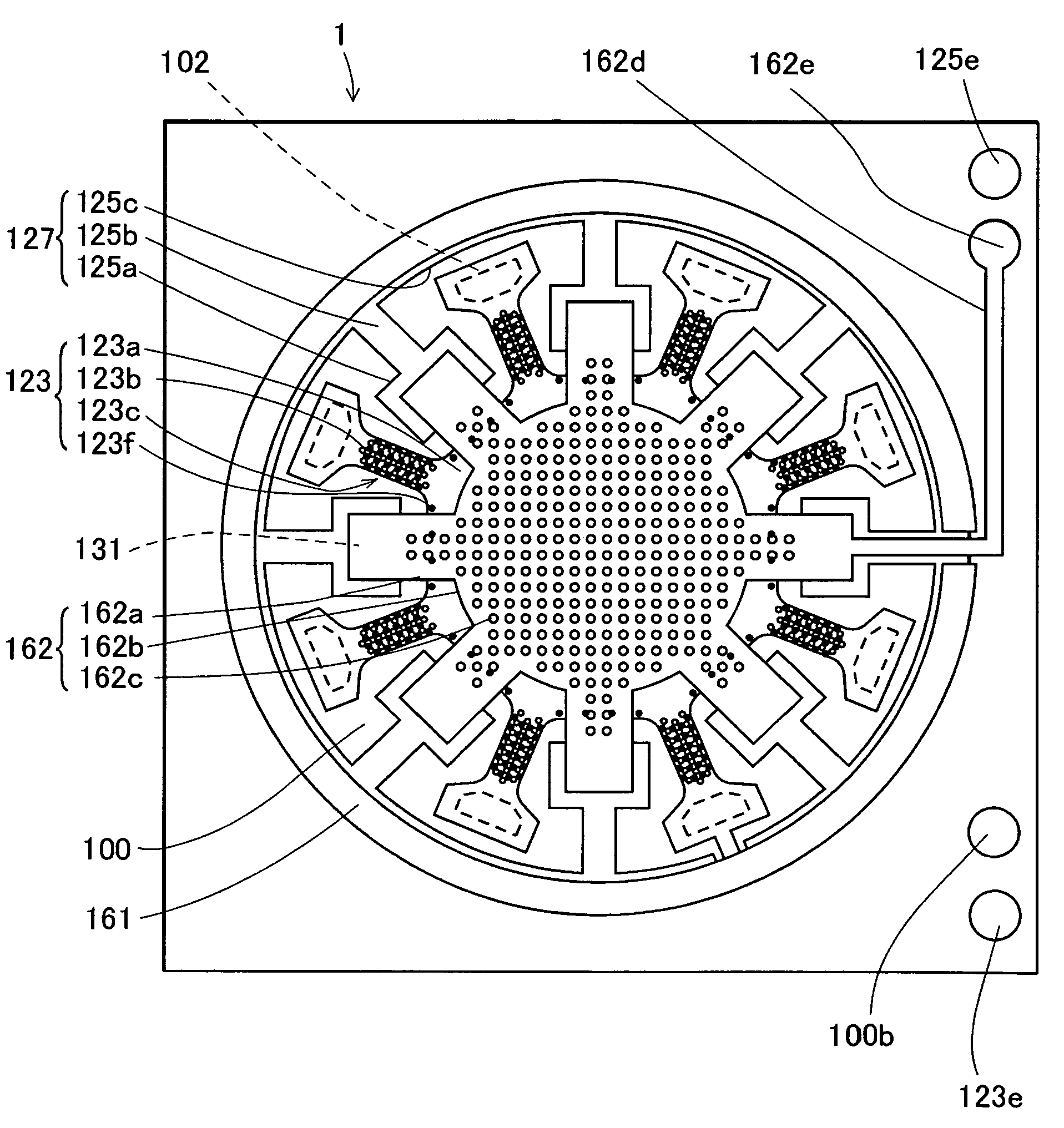
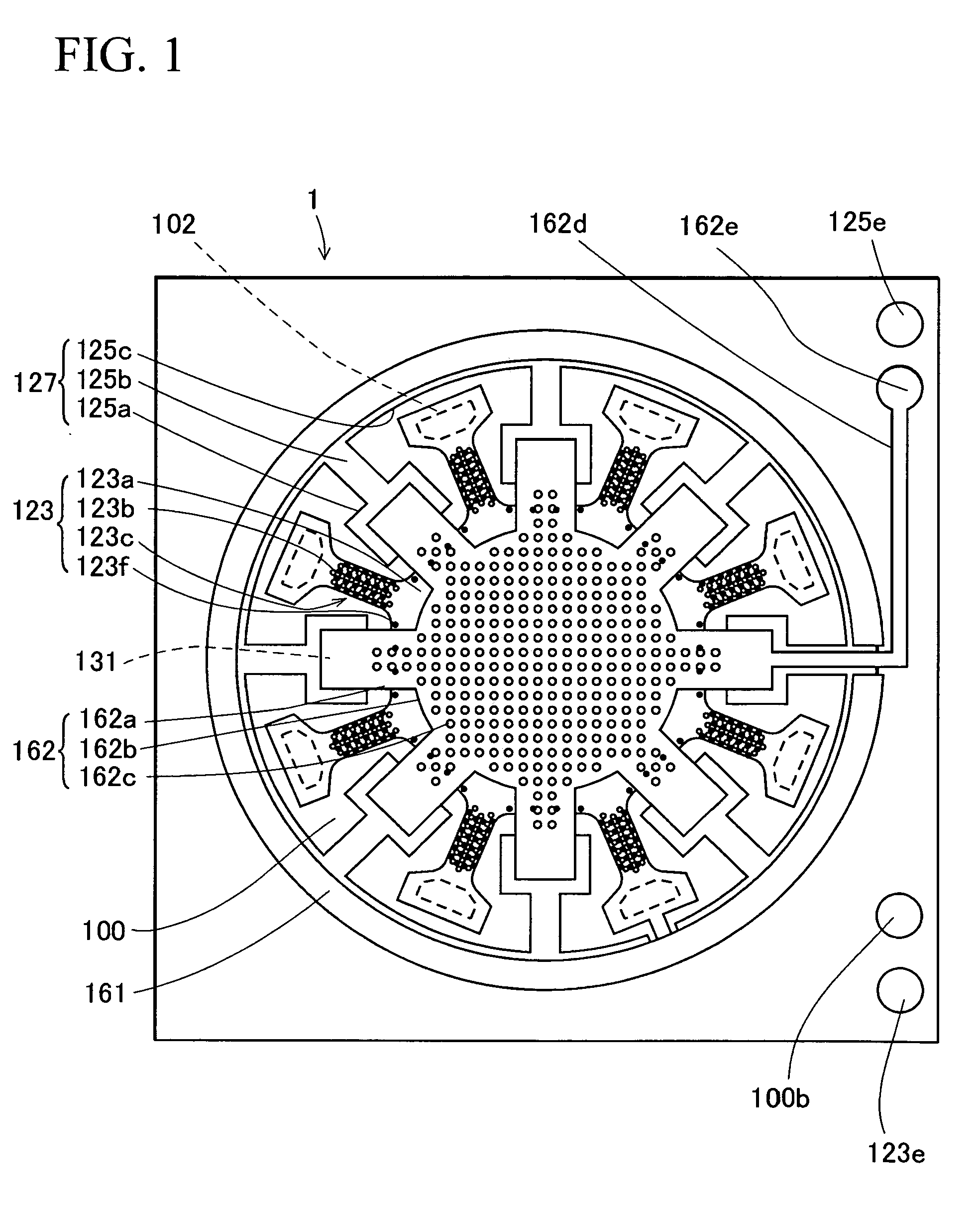
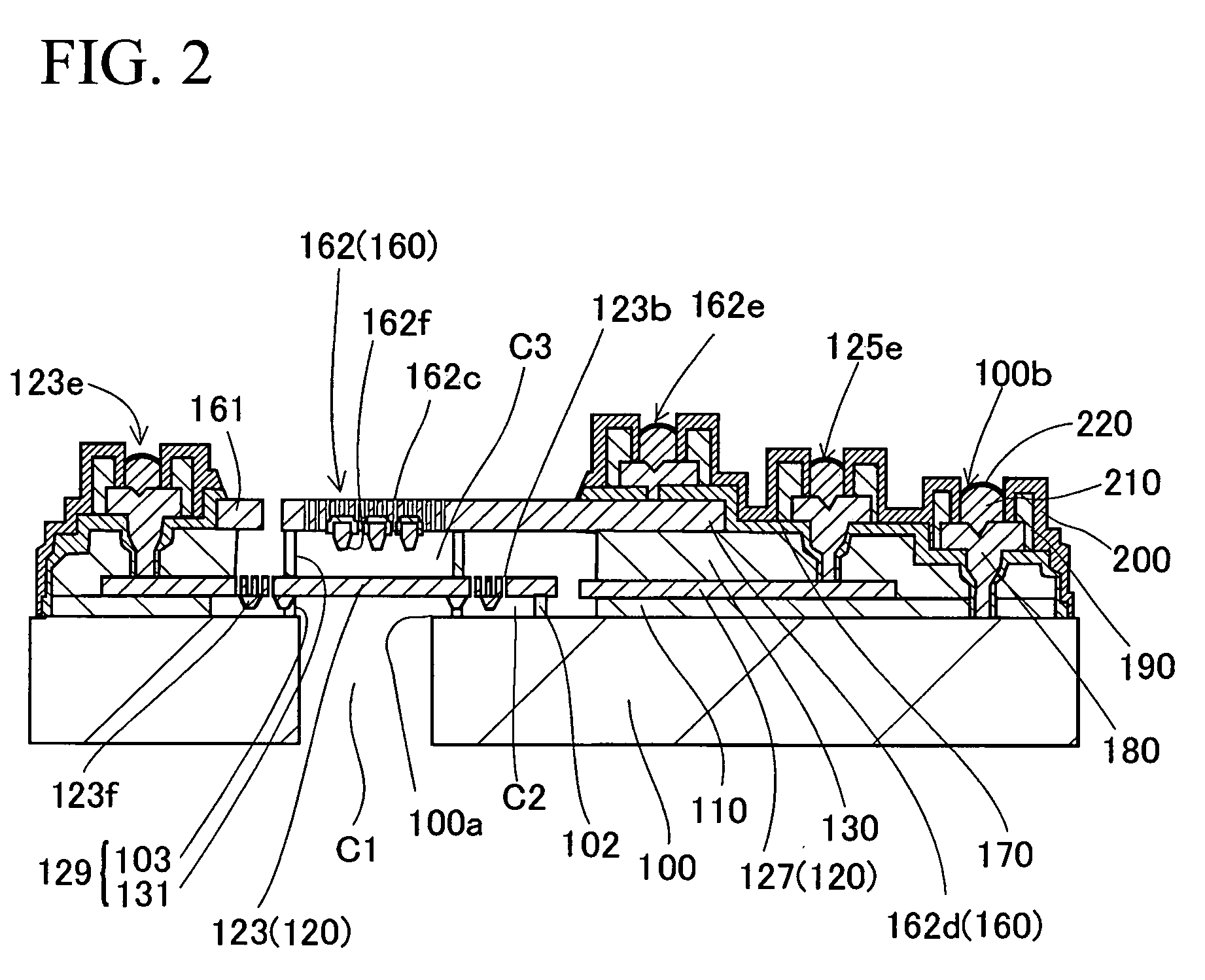
[0061]FIG. 1 is a plan view showing a sensor chip of a condenser microphone 1 having an MEMS (Micro-Electro-Mechanical System) structure in accordance with a third embodiment of the present invention. FIG. 2 is a longitudinal sectional view showing the constitution of the condenser microphone 1. FIG. 3 is an exploded perspective view showing the laminated structure of the condenser microphone 1. FIGS. 21 and 22 are cross-sectional views showing prescribed parts of the condenser microphone 1.

[0062]The condense microphone 1 is constituted of the sensor chip and a control chip (which includes a power supply circuit and an amplifier, not shown), both of which are encapsulated in a package (not shown).

[0063]The sensor chip of the condenser microphone 1 is formed by depositing multiple films on a substrate 100, namely, a lower insulating film 110, a lower conductive film 120, an upper insulating film 130, an upper conductive film 160, and a surface insulating film 170. ...

second embodiment

2. Second Embodiment

[0113]Next, a condenser microphone 2 according to a second embodiment of the present invention will be described with reference to FIGS. 23 to 31, wherein parts identical to those used in the condenser microphone 1 of the first embodiment shown in FIGS. 1 to 22 are designated by the same reference numerals; hence, the detailed constitutions and operations thereof will be described briefly.

[0114]FIG. 23 shows a sensor chip corresponding to an MEMS structure of a condenser microphone 2 of the second embodiment, the longitudinal sectional view of which is shown in FIG. 2. FIGS. 21 and 22 show cross sections of prescribed parts of the condenser microphone 2. The condenser microphone 2 is constituted of the sensor chip as well as a circuit chip (not shown) including power circuitry and amplification circuitry, and a package (not shown) containing these elements.

[0115]In a similar manner to the sensor chip of the condenser microphone 1 of the first embodiment, the sens...


PUM


Abstract

A vibration transducer includes a substrate, a diaphragm formed using deposited films having conductive property, which has a plurality of arms extended from the center portion in a radial direction, a plate formed using deposited films having conductive property, and a plurality of diaphragm supports formed using deposited films, which join the arms so as to support the diaphragm above the substrate with a prescribed gap therebetween. A plurality of bumps is formed in the arms of the diaphragm so as to prevent the diaphragm from being attached to the substrate or the plate. When the diaphragm vibrates relative to the plate, an electrostatic capacitance therebetween is varied so as to detect variations of pressure applied thereto. In addition, a plurality of diaphragm holes is appropriately aligned in the arms of the diaphragm so as to improve the sensitivity while avoiding the occurrence of adherence.

Description

BACKGROUND OF THE INVENTION[0001]1. Field of the Invention[0002]The present invention further relates to vibration transducers such as miniature condenser microphones serving as MEMS sensors.[0003]The present application claims priority on Japanese Patent Application No. 2007-256908 and Japanese Patent Application No. 2007-280315, the contents of which are incorporated herein by reference in their entirety.[0004]2. Description of the Related Art[0005]Conventionally, various types of condenser microphones have been developed and disclosed in various documents as follows:[0006]Patent Document 1: Japanese Patent Application Publication No. H09-508777[0007]Patent Document 2: Japanese Patent Application Publication No. 2004-506394[0008]Patent Document 3: U.S. Pat. No. 4,776,019[0009]Non-Patent Document 1: The paper entitled “MSS-01-34” published by the Japanese Institute of Electrical Engineers[0010]It is conventionally known that miniature condenser microphones (referred to as MEMS micr...

Claims


Application Information

Patent Timeline
IPC IPC(8): H04R11/04
CPCB81B3/0008B81B2201/0257H04R1/04H04R3/06H04R7/04H04R2307/207H04R19/005H04R19/04H04R31/00H04R2307/201H04R7/20
Inventor SUZUKI, TAMITOSUZUKI, YUKITOSHISUZUKI, TOSHIHISASATO, AKIYOSHI
Owner YAMAHA CORP
Why Eureka
Try Eureka