Electrically powered pump

a technology of electric motors and winding wires, which is applied in the direction of pumping, positive displacement liquid engines, machines/engines, etc., can solve the problems of winding wire corrosion, corrosion of winding wires, and corrosion of copper conductive bodies,

Inactive Publication Date: 2009-07-30
DENSO CORP
View PDF0 Cites 26 Cited by
  • Summary
  • Abstract
  • Description
  • Claims
  • Application Information

AI Technical Summary

Benefits of technology

[0012]Thus, it is an objective of the present invention to provide an electrically powered pump that has an electric motor arran

Problems solved by technology

However, when the conventional electrically powered pump was used as the urea water pump as it is, corrosion of winding wires, which are described below, became a problem.
The inventor found that it is further required to take measures against corrosion of the winding wires, since urea water easily permeates the above-mentioned covering resin and the insulator compared with mere water

Method used


Image

  • Electrically powered pump
  • Electrically powered pump
  • Electrically powered pump

Examples


Embodiment Construction

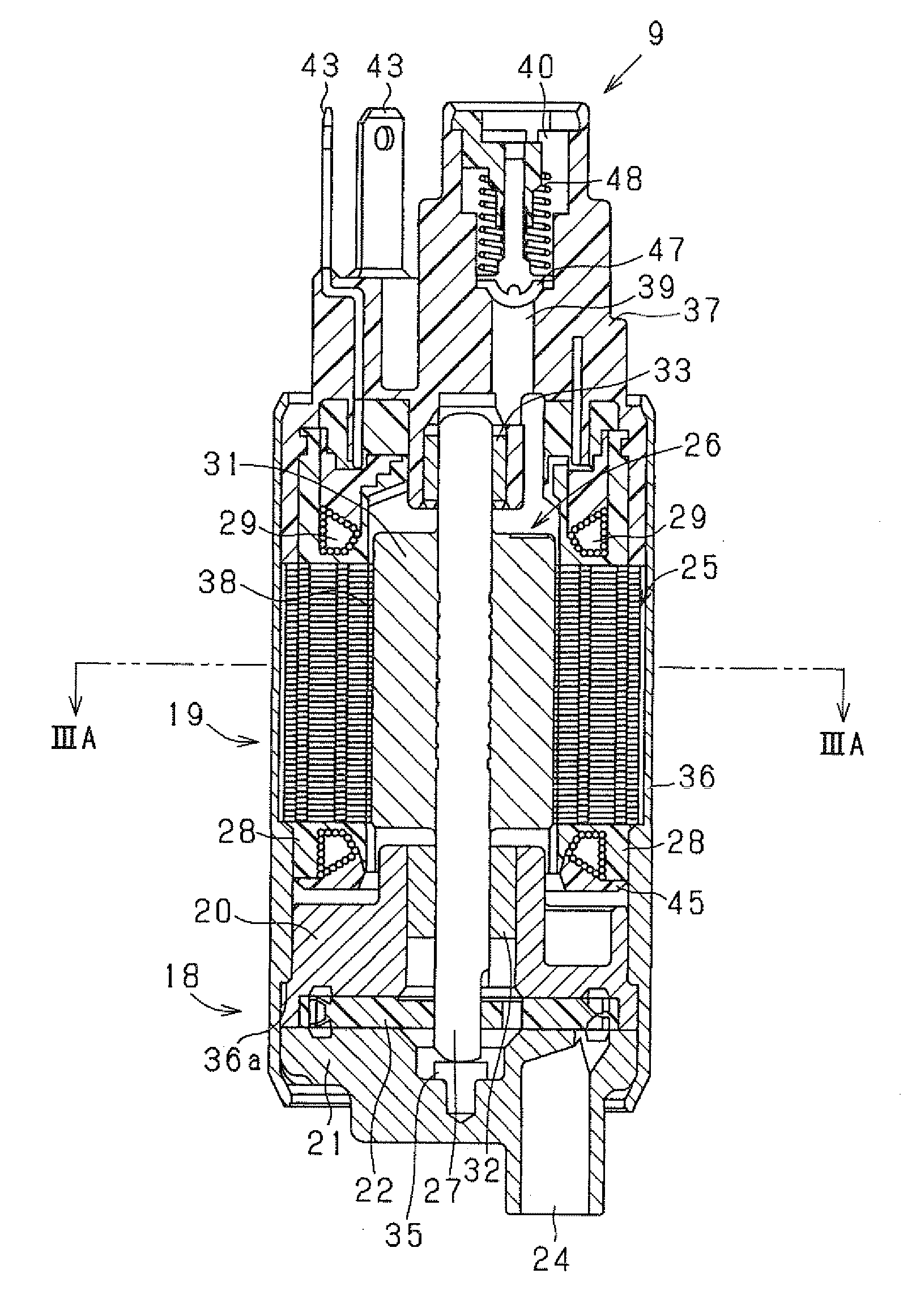
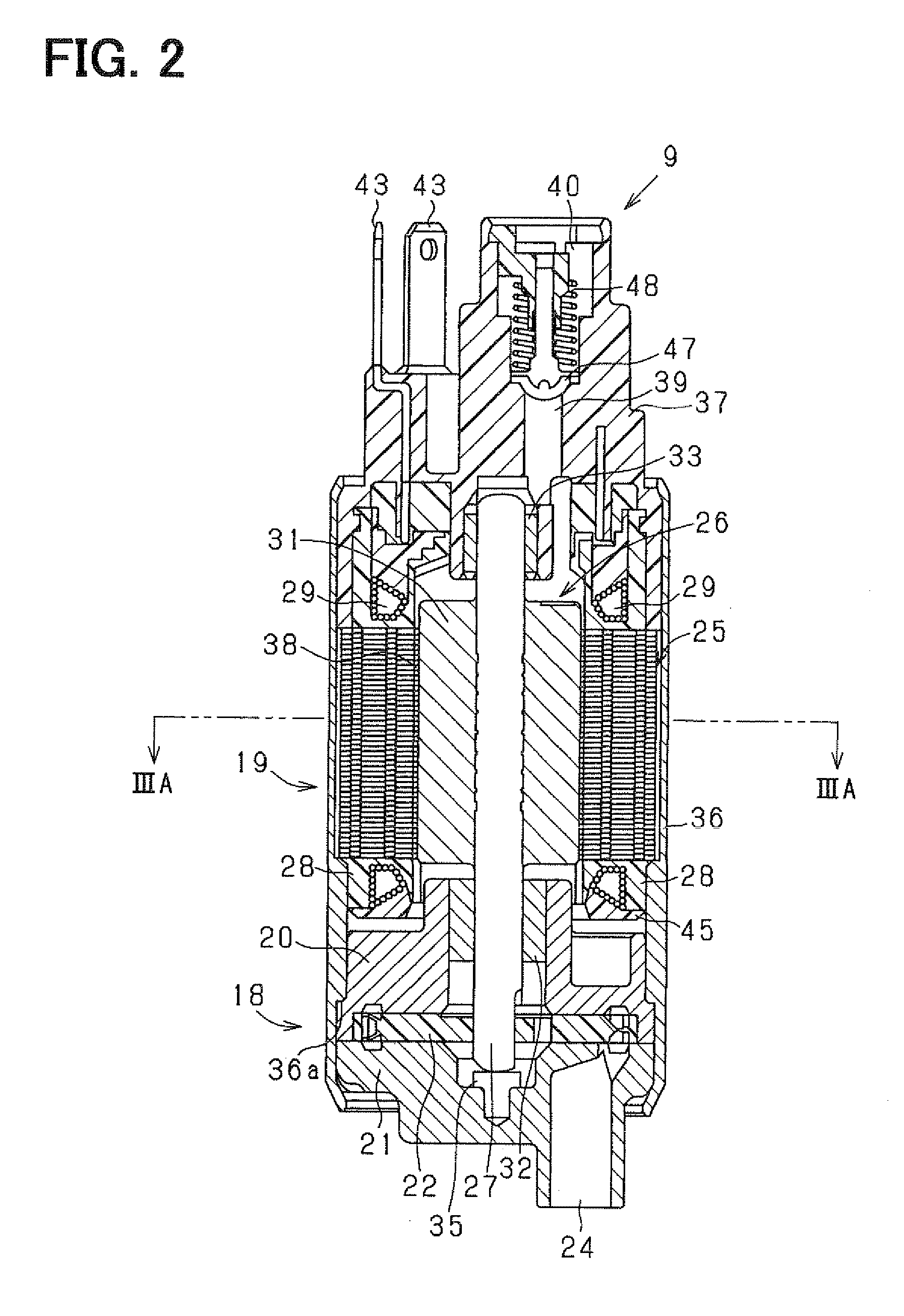
[0022]An electrically powered pump according to one embodiment of the present invention will be described hereafter, with reference to the accompanying drawings.

[0023]The electrically powered pump according to the present embodiment is applied to a urea water pump that pumps urea water solution (hereafter referred to just as urea water) that contains urea as a reducing agent. The urea water discharged from the urea water pump is pressurized and pumped to an addition valve. The addition valve is so installed as to inject the urea water in an exhaust gas flow in an exhaust passage of a diesel engine (hereafter referred to as engine), which is an internal combustion engine.

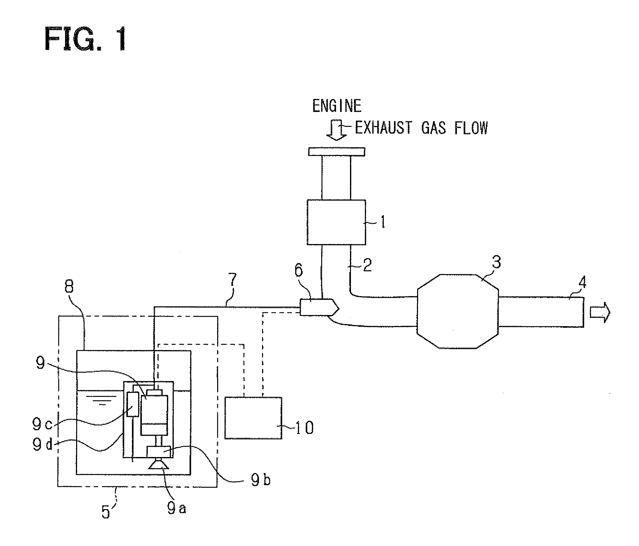
[0024]FIG. 1 schematically shows an entire construction of a urea SCR system in which the urea water pump (electrically powered pump) according to the present embodiment is incorporated. FIG. 1 depicts an exhaust emission control device in which exhaust gas discharged from the engine of a vehicle (not shown) is clean...


PUM


Abstract

An electrically powered pump includes a pump arrangement that pumps a liquid, and an electric motor arrangement that has a stator and a rotor that are installed on a passage through which the liquid pumped by the pump arrangement flows. At least one of the stator and the rotor has a winding wire that generates a magnetic field when it is energized to rotate the rotor with respect to the stator to drive the pump arrangement. The winding wire has a conductive body through which an electric current passes and an insulation body that insulates the conductive body. The conductive body is made of a material predominantly composed of carbon. Thereby, the liquid pumped by a pump arrangement is prevented from corroding the winding wire.

Description

CROSS REFERENCE TO RELATED APPLICATION[0001]This application is based on and incorporates herein by reference Japanese Patent Application No. 2008-017085 filed on Jan. 29, 2008.BACKGROUND OF THE INVENTION[0002]1. Field of the Invention[0003]The present invention relates to an electrically powered pump that has an electric motor arrangement for driving a pump arrangement.[0004]2. Description of Related Art[0005]In recent years, selective reduction (SCR: Selective Catalytic Reduction) type urea SCR system is under development, and partly put into actual use. The SCR system is installed in an internal combustion engine (especially diesel engine) of a vehicle, etc., to reduce NOx (nitrogen oxides) in exhaust gas.[0006]In the urea SCR system, a selective reduction type NOx cleaning catalyst (SCR catalyst) is installed in an exhaust pipe of an internal combustion engine, and a urea water addition valve, which adds urea water (urea water solution) as a reducing agent to the exhaust gas in ...

Claims


Application Information

Patent Timeline
IPC IPC(8): F04D13/06F01N3/10
CPCF01N3/2066F01N2610/02F01N2610/1406F01N2610/1433H02K5/12F04D13/06H02K3/02H02K3/44F04D5/002Y02A50/20
Inventor SUZUKI, KAZUNORI
Owner DENSO CORP
Why Eureka
Try Eureka