Air conditioning system for vehicle

a technology of air conditioning system and vehicle, which is applied in the direction of refrigeration components, transportation and packaging, light and heating equipment, etc., can solve the problems of complex configuration of heat-pump type cooling unit, and system inability to achieve air-cooling, etc., to achieve the effect of easy discharg

Inactive Publication Date: 2009-08-06
CALSONIC KANSEI CORP
View PDF1 Cites 51 Cited by
  • Summary
  • Abstract
  • Description
  • Claims
  • Application Information

AI Technical Summary

Benefits of technology

[0010]Therefore, an object of the present invention is to provide a dual-type air conditioning system for a vehicle that achieves air-heating or air-cooling selectively by using a heat-pump type cooling unit with configuration of the heat-pump type cooling unit being made simplified. In addition, general configuration of the air conditioning system can be also simplified.
[0031]According to this configuration, the vehicle compartment can be cooled efficiency because heated air can be discharged to the outside of the vehicle compartment during air-cooling. Heated air passing through the rear heater core can be discharged more easily even with a simple structure than heated air passing through the front heater core because negative pressure occurs at a rear side of a vehicle body when a vehicle running.

Problems solved by technology

As a result, configuration of the heat-pump type cooling unit must be complex.
Configuration of the heat-pump type cooling unit must be further complicated because more of the bypass paths and the changeover valves are needed when such a dual-type air conditioning system is applied to a large-compartment vehicle.
However, the system cannot achieve air-cooling.

Method used


Image

  • Air conditioning system for vehicle
  • Air conditioning system for vehicle
  • Air conditioning system for vehicle

Examples


Embodiment Construction

[0042]Hereinafter, embodiments according to the present invention will be explained with reference to drawings.

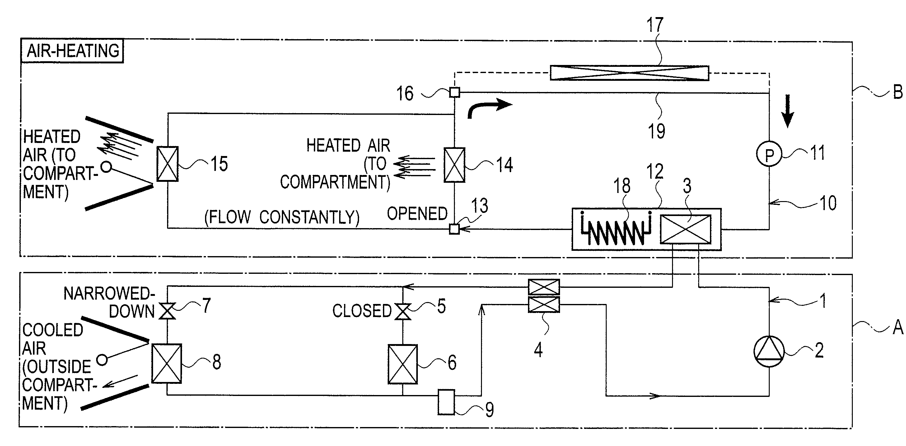
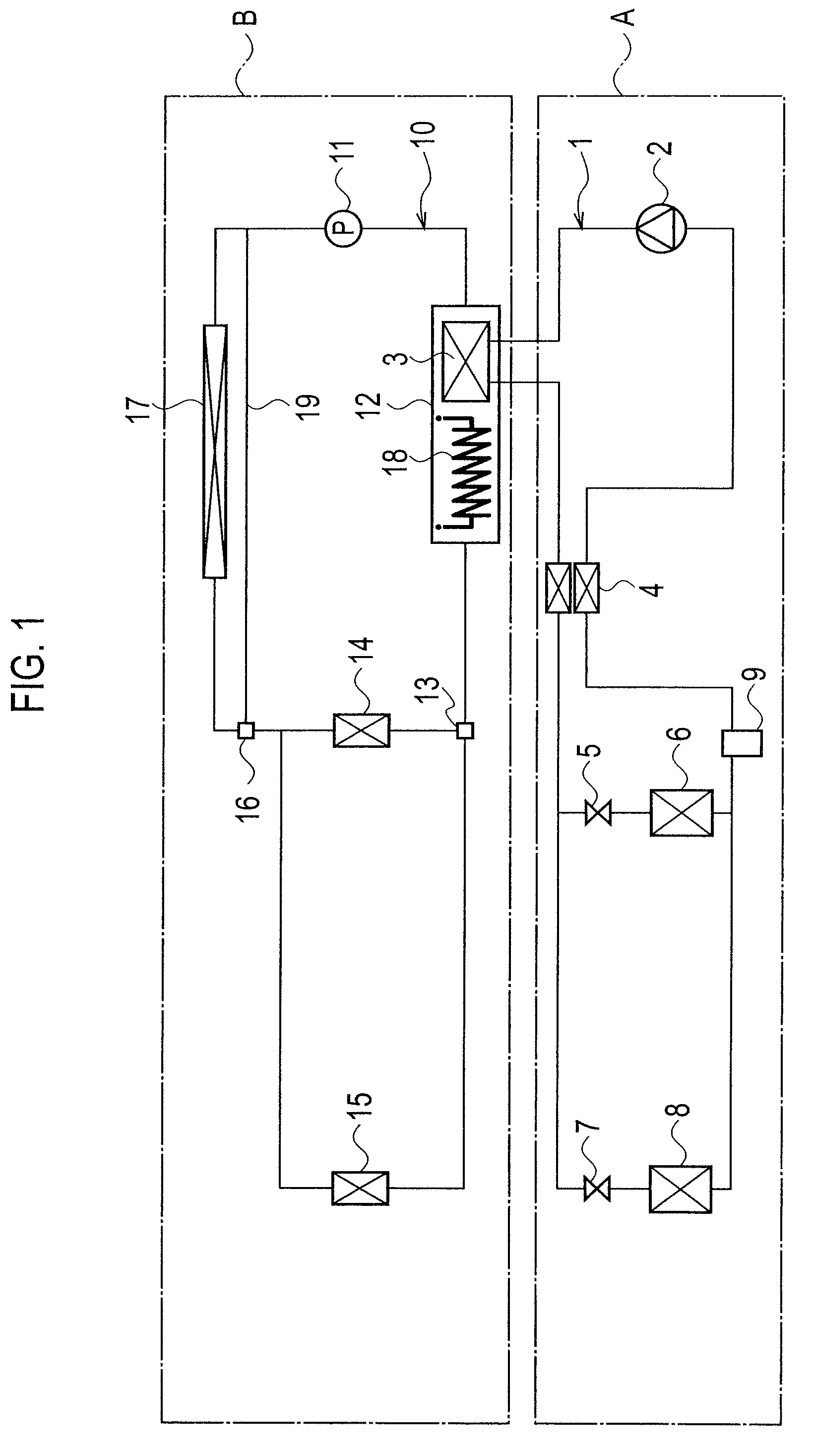
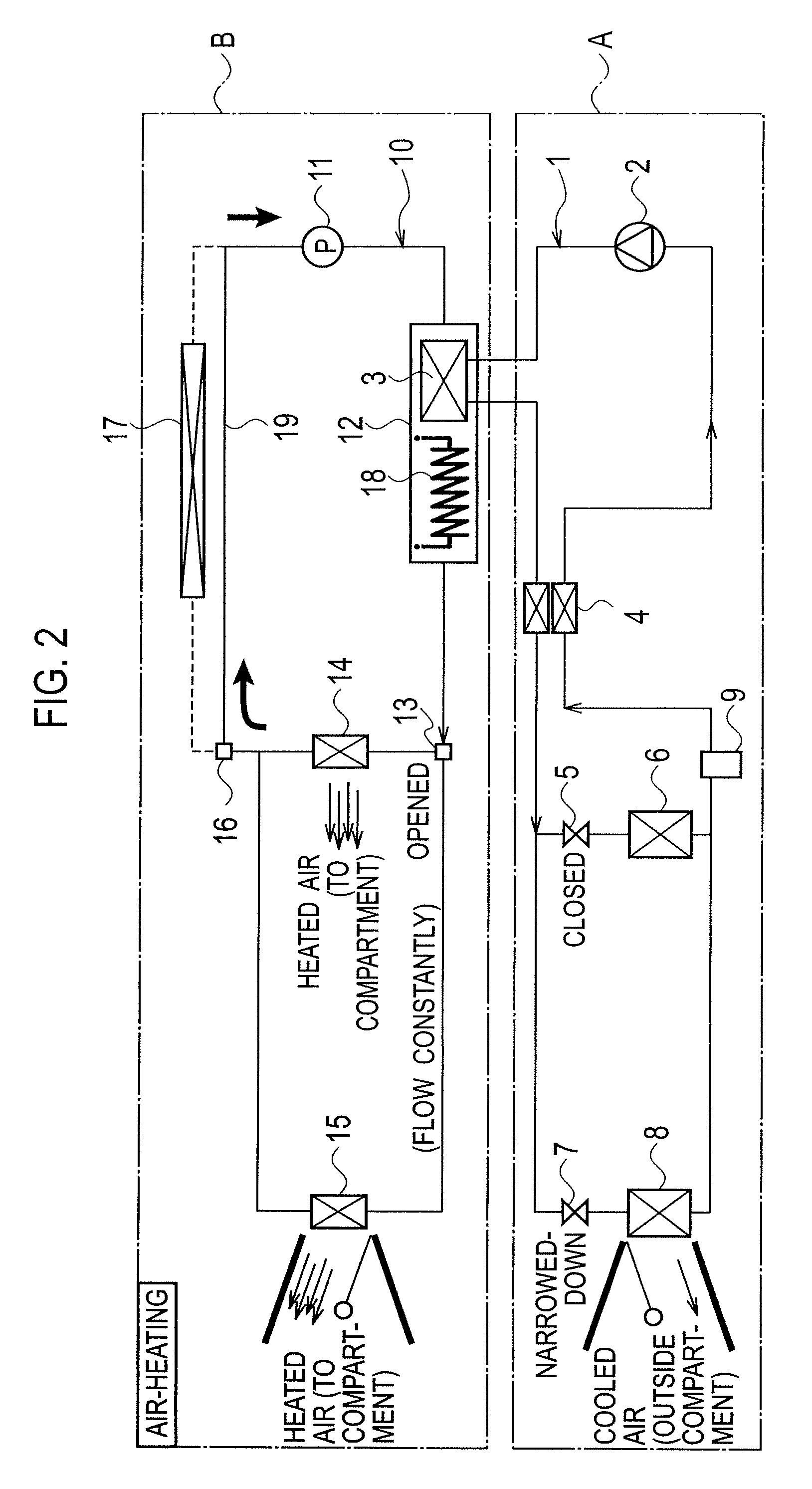
[0043]A first embodiment of an air conditioning system for a vehicle according to the present invention will be explained with reference to FIGS. 1 to 7. As shown in FIG. 1, the air conditioning system is combined of a heat-pump type cooling unit A and an air-heating circulation unit B.

[0044]The heat-pump type cooling unit A includes a first circulation path 1. The first circulation path 1 is filled with first refrigerant (CO2). A compressor 2, a water-cooled condenser 3, an internal heat exchanger 4, a front expansion valve (front expansion unit) 5, a front evaporator 6, a rear expansion valve (rear expansion unit) 7, a rear evaporator 8 and a accumulator 9 are provided on the first circulation path 1. A flow path section on which the front expansion valve 5 and the front evaporator 6 are provided and another flow path section on which the rear expansion valve 7 and the re...


PUM


Abstract

An air conditioning system includes an air-cooling unit and an air-heating unit. On a first path in the cooling-unit, provided are a compressor for first refrigerant, a condenser for the first refrigerant, front and rear expansion units for the first refrigerant, and an front and rear evaporators to cool air. On a second path in the air-heating unit, provided are a pump for second refrigerant, and front and rear heater cores for the second refrigerant. The condenser is located also on the second path to achieve heat-exchanging between the first refrigerant and the second refrigerant. During air-heating, air heated by the front and rear heater cores is supplied to a vehicle compartment as conditioned air. During air-cooling, air cooled by the front and rear evaporator is supplied to the vehicle compartment as conditioned air.

Description

BACKGROUND OF THE INVENTION[0001]1. Field of the Invention[0002]The present invention relates to a dual-type air conditioning system for a vehicle that can achieve air-heating or air-cooling selectively.[0003]2. Description of Related Art Japanese Patent Application Laid-Open Number 2002-98430 (Patent Document) discloses a conventional air conditioning system (fourth embodiment: FIGS. 9 and 10). The air conditioning system includes a heat-pump type cooling unit and an air-heating circulation unit. The heat-pump type cooling unit has a first circulation path along which first refrigerant circulates. The air-heating circulation unit has a second circulation path along which second refrigerant circulates.[0004]A compressor, a heat-radiating side of an internal heat exchanger, an in-compartment heat exchanger, an expansion valve and an external heat exchanger are provided on the first circulation path in the heat-pump type cooling unit. Variety of bypass paths and many of changeover val...

Claims


Application Information

Patent Timeline
Patent Type & Authority Applications(United States)
IPC IPC(8): B60H1/32F25B7/00B60H1/02F25B41/04
CPCB60H1/0005B60H1/323B60H1/00899B60H2001/00178
Inventor YOSHIOKA, HIROKI
Owner CALSONIC KANSEI CORP
Why Eureka
Try Eureka