Method for manufacturing a heat exchanger

a heat exchanger and manufacturing method technology, applied in indirect heat exchangers, lighting and heating apparatuses, laminated elements, etc., can solve the problems of increased fluid flow, increased energy needed to circulate fluid, and increased risk of system malfunction, so as to reduce the risk of edges deteriorating by melting during welding and achieve the effect of very efficient welding operation

Inactive Publication Date: 2009-08-06
DANTHERM AIR HANDLING
View PDF25 Cites 14 Cited by
  • Summary
  • Abstract
  • Description
  • Claims
  • Application Information

AI Technical Summary

Benefits of technology

[0027]Thereby, an efficient heat exchanger can quickly be assembled from the heat exchanger plates. The joining operation does not require any additional parts, and the joined stack of heat exchanger plates is a stable construction. Also, the stacking and joining steps enable easy modification of the heat exchanger's size and thus capacity, as it is simply a matter of changing the number of heat exchanger plates in each stack. In contrast to known heat exchangers, there is no encapsulation around the heat exchanger plate that has to be adapted to the number of heat exchanger plates employed in the heat exchanger. If very large modifications are needed this can also be achieved by the method by changing the thickness of the sheets, the material of the sheets or the type of mould used in the shaping step. Hence, the invention discloses a method for producing heat exchangers in a cheap, fast and versatile way.
[0050]Heating the sheets prior to shaping them decreases the force needed to carry out the shaping, which enables a cheaper and faster shaping. Using the combination of vacuum and pressure to fasten and shape pre-heated sheets in a mould is a shaping process that is versatile enough to shape a heat exchanger plate with competitive heat exchange capabilities, while at the same time being cheap and fast enough to enable low-cost mass-production. The vacuum applied is preferably as close to a perfect vacuum as possible, even though the principle can also work at a partial vacuum. The speed of manufacturing that can be achieved with this method is well below 5 seconds per heat exchanger plate.

Problems solved by technology

Secondly, heat can move faster to and from the contact surface if the heat convection in the fluid is increased.
A turbulent flow increases the pressure loss in the heat exchanger, which increases the amount of energy needed to circulate the fluid.
Furthermore, for some applications it is relevant to prevent leakage of dangerous fluids such as refrigerants to the surroundings, which could result in hazardous contamination and system malfunctions.
To comply with all these requirements, most current heat exchanger designs are complex constructions, for example comprising several ducts, grooves, and layers.
In some cases, current heat exchangers are furthermore manufactured from a material that is expensive in itself or impacts the cost of manufacturing considerably.
As the heat exchangers disclosed by the current art are complex constructions, the manufacturing of them tends to be quite complex with several steps and manual interventions.
The many steps and manual interventions entail several hazards to personnel security and impact the manufacturing costs considerably.
The heat exchangers' costs can easily amount to a considerable share of the total product cost.
If the design of the item to be produced is highly complex, the manufacturing cost is considerable as the complex design necessitates high machinery investment, high tool investments, long process times, high scrap rates, etc.
Furthermore, the manufacturing cost of the product which the heat exchanger is to become a component in, can be highly impacted on how suitable the heat exchanger is for mounting in assemblies.
The current art discloses heat exchangers with the disadvantage that the cost of manufacturing them is considerable due to one or more cost-impacting factors being sub optimal.
Also, the current art discloses several manufacturing methods, which if applied to manufacturing of heat exchangers, would require considerable compromises in the characterising properties of the heat exchanger design.
One of these compromises is that the manufactured heat exchangers are complicated to mount in assemblies.

Method used


Image

  • Method for manufacturing a heat exchanger
  • Method for manufacturing a heat exchanger
  • Method for manufacturing a heat exchanger

Examples


Embodiment Construction

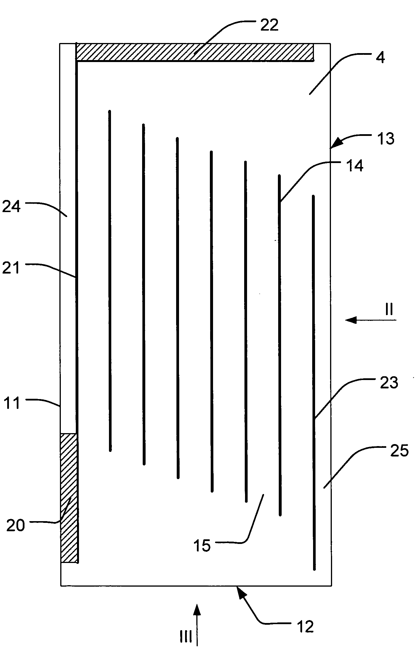
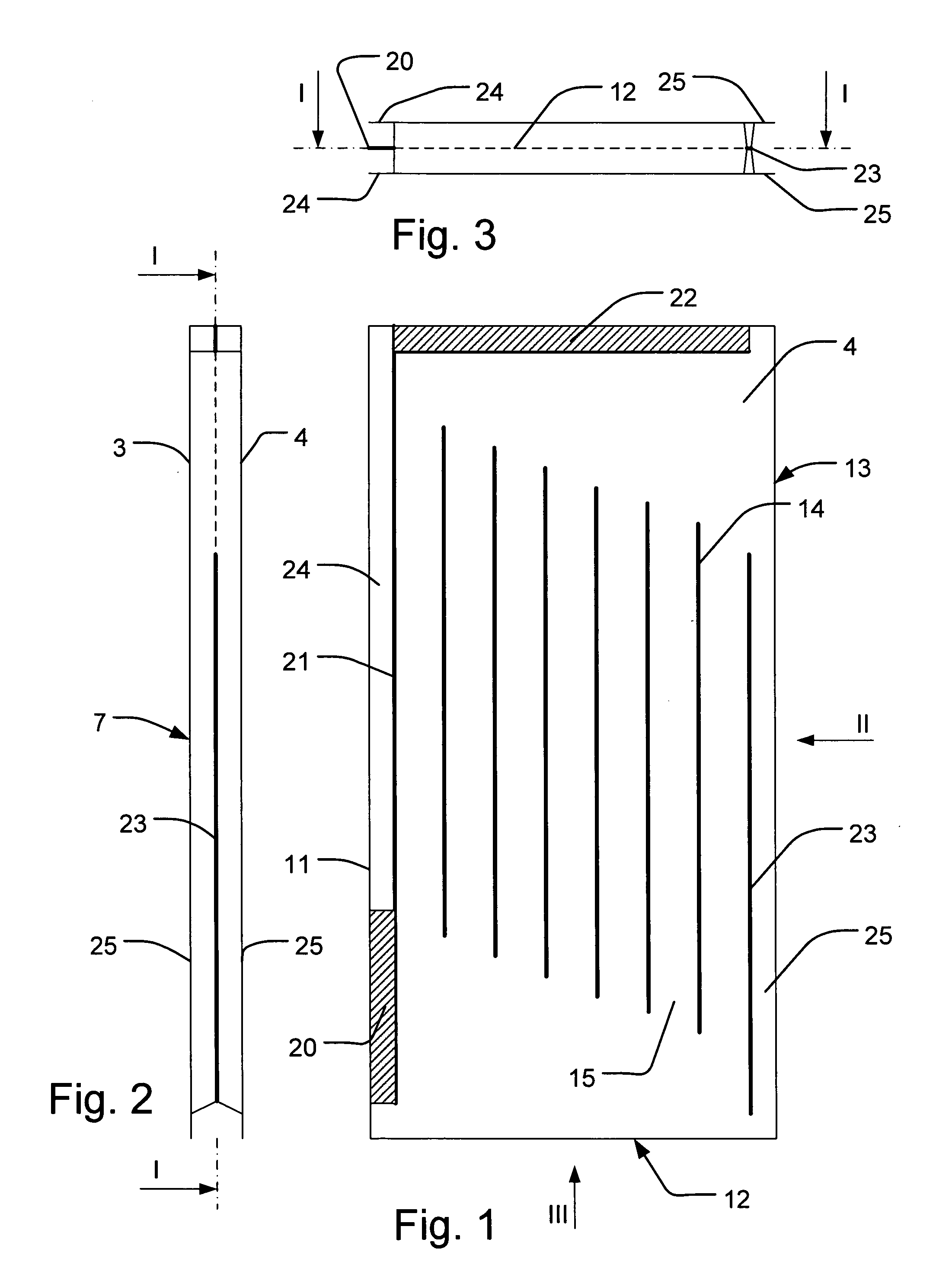
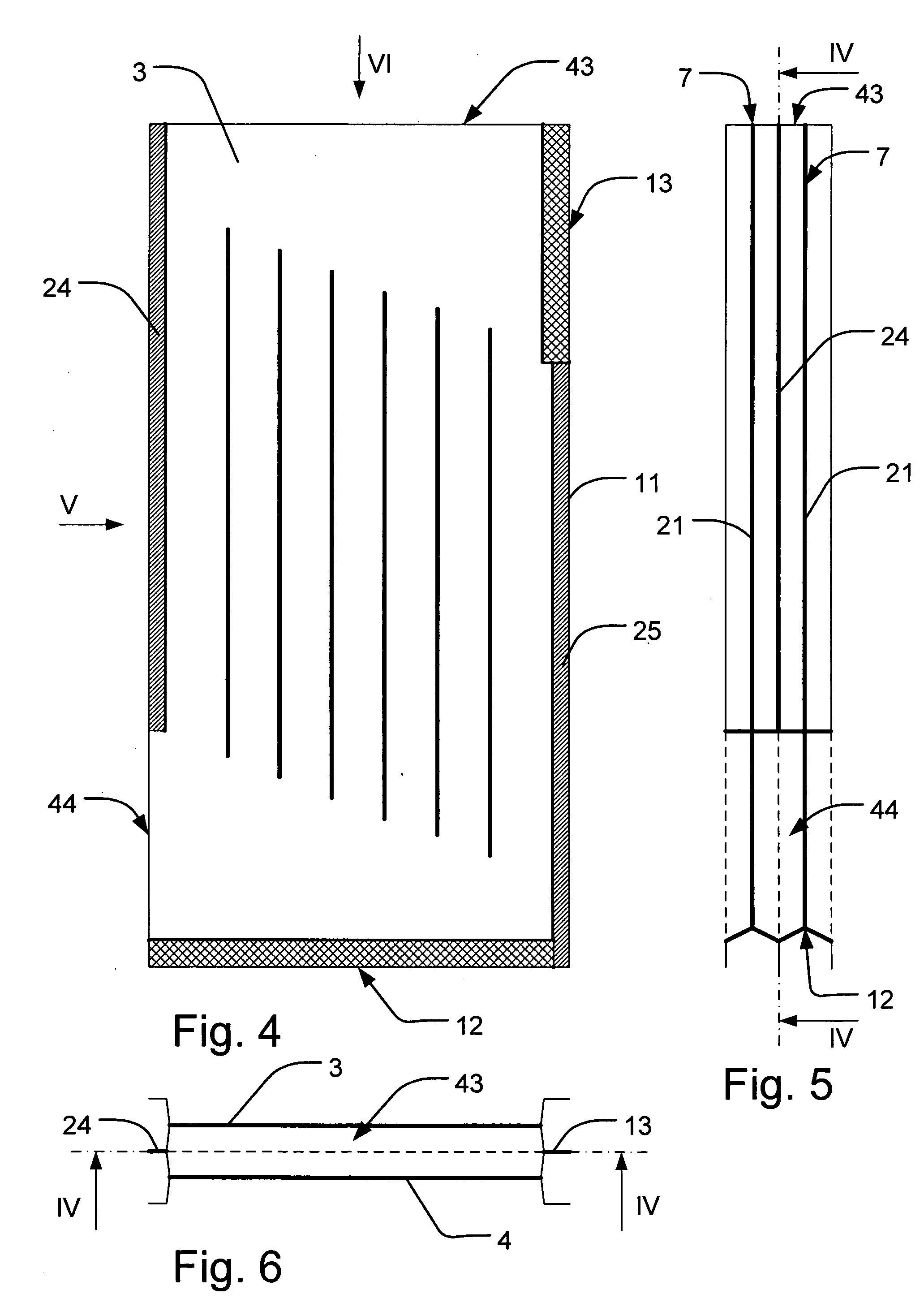
[0067]FIG. 7 shows a production line 1 for manufacturing of a heat exchanger plate 7 from plastic material according to the invention. An upper and a lower sheet element 3, 4 of plastic material are fed to the production line. The plastic material is fed from two coils 2 to make for a simple but automated feeding. The feeding can also be done as single sheets. Furthermore, the sheets can advantageously be fed in two layers to a not shown conveyor belt to prepare in an advantageous way for succeeding shaping. A further advantage of feeding two layers of sheets from two coils is that it can happen automatically. Additionally, feeding the material this way can be done at very high speed.

[0068]The fed sheet elements 3, 4 are subsequently heated to a forming temperature in a heating station 5 of the production line 1. The heating is preferably done in a heating means through which the sheets are moved by a not shown conveyor belt. Heating the sheets elements can also be done by rolling t...


PUM

PropertyMeasurementUnit
pressureaaaaaaaaaa
lengthaaaaaaaaaa
lengthsaaaaaaaaaa

Abstract

The method for manufacturing a heat exchanger from a plastic material comprises feeding of at least two sheet elements, and, by means of shaping means, shaping of said sheet elements to form heat exchanger plates. The shaping means are adapted to also undertake joining the sheet elements partly along edges so that a fluid inlet and outlet are created, whereby the sheet elements are pressed together. The heat exchanger plates are stacked and joined to a heat exchanger. The stack of heat exchanger plates is welded so that the fluid inlets are fluid outlets of the respective heat exchanger plates are combined to form a common fluid inlet and a common fluid outlet, and the sides of the heat exchanger plates are welded together, so that a fully functional heat exchanger is manufactured with plastic sheets as the only raw material.

Description

[0001]This application is entitled to the benefit of, and incorporates by reference essential subject matter disclosed in PCT Application No. PCT / DK2007 / 000387 filed on Aug. 28, 2007, which claims priority to Denmark Application No. PA 2006 01113 filed Aug. 28, 2006.BACKGROUND OF THE INVENTION[0002]1. Technical Field[0003]The present invention relates to a method for manufacturing a heat exchanger from a plastic material, said method comprising the steps of:[0004]feeding of at least two sheet elements made from said plastic material,[0005]by means of shaping means, shaping of said sheet elements to form a number of heat exchanger plates, whereby said shaping means are adapted to also undertake joining the sheet elements partly along edges so that a fluid inlet and a fluid outlet are created, whereby the sheet elements are pressed together, and[0006]two or more heat exchanger plates are stacked on top of one another.[0007]2. Background Information[0008]Heat exchanging equipment is wi...

Claims


Application Information

Patent Timeline
Patent Type & Authority Applications(United States)
IPC IPC(8): F28F7/00B21D53/04B29D99/00
CPCB29C65/02Y10T29/49366B29C66/022B29C66/1122B29C66/137B29C66/43B29C67/0044B29C2791/001B29C2791/006B29C2791/007B29L2031/18F28D9/0037F28F3/048F28F21/065B29C65/7891F28F3/14B29C51/267B29C49/0047B29C65/00B29C66/83221B29C65/18B29C66/0222B29C66/02241F28F2250/104B29C49/0691B29C49/42069B29C49/4207
Inventor KRISTENSEN, ERIKJENSEN, DENNIS NALDAL
Owner DANTHERM AIR HANDLING
Why Eureka
Try Eureka