Tilt angle sensor and detection-target device comprising the same

a technology of tilt angle sensor and detection target, which is applied in the direction of instruments, nanomagnetism, magnetic measurements, etc., can solve the problems of likely noise detection, and achieve the effect of improving sensitivity and accuracy and simple structur

Inactive Publication Date: 2009-08-06
SAE MAGNETICS (HK) LTD
View PDF2 Cites 16 Cited by
  • Summary
  • Abstract
  • Description
  • Claims
  • Application Information

AI Technical Summary

Benefits of technology

[0009]It is therefore an object of the present invention to improve the inconveniences of the conventional cases and, in particular, to provide a tilt angle sensor that is capable of detecting, with high sensitivity and high accuracy, acceleration, a tilt angle, and the like of a device to which the sensor is mounted and also capable of reducing the size and cost with a simple structure.
[0012]With the present invention, first, when there is acceleration or a tilt generated along the direction of the flexibility of the spring member, the spring member is bent and the magnetic field generating device mounted to the free end of the spring member is shifted in the bending direction. Upon this, the direction of the magnetic field generated by the magnetic field generating device is changed as well. Through detecting the change in the direction of the magnetic field by the magnetic field detecting device, it is possible to detect a change such as a tilt or acceleration at least in one axial direction. In the meantime, since the spring member is formed to be easily oscillated and highly sensitive, it is likely to catch a noise such as an external impact that oscillates the spring member, particularly, a noise that is close to the resonance frequency. However, the oscillation can be promptly resolved by the damping device in a short time. Therefore, continuation of the oscillation of the spring member can be suppressed, thereby making it possible to detect the tilt and the like that are to be detected with high accuracy and high sensitivity. With the above, it becomes possible to constitute the small-sized and low-cost sensor with a simple structure. At the same time, it is possible to suppress influences of the noise while improving the sensitivity of the sensor for detecting the tilt angle and the acceleration. Particularly, by providing the damping device at the tip of the free end of the spring member, it is possible to improve the sensitivity and accuracy of detection still further by damping the oscillation in a shorter time through effectively applying the damping force while allowing the move of the spring member caused due to generation of a tilt or acceleration.
[0013]Further, it is desirable for the spring member to be formed with a plate-type member whose plate thickness in the bending direction of the free end is formed thin. Furthermore, it is desirable for the length thereof in the longitudinal direction that is perpendicular to the bending direction to be formed long to provide a low resonance frequency. With this, the resonance frequency becomes low, and the spring member becomes easily bent in the bending direction. That is, the tilt and the external force can be detected with high sensitivity and, as described above, the oscillation generated in the spring member due to a noise can be resolved by the damping device in a short time. Therefore, it becomes possible to detect the tilt and the acceleration with high sensitivity while suppressing influences of the noise. Further, by constituting the sensor to have high sensitivity in the manner as described above, it is also possible to suppress influences of a temperature drift caused by the magnetic field detecting device. That is, because it is possible to obtain a large detection amount by the magnetic field detecting device due to the improved sensitivity, highly accurate detection can be achieved even if there is the temperature drift generated by the magnetic field detecting device. Therefore, the quality of the sensor can be improved.
[0015]By providing the viscous member between the movable part of the spring member or the like and another fixed member in this manner, it is possible to achieve the damping device with a simple structure. Particularly, by using the gel-type member to have the movable part of the spring member or the like dipped therein, it becomes possible to give a damping force to the oscillation of the spring member efficiently so as to resolve the oscillation in a short time. Therefore, a highly sensitive sensor can be achieved at a low cost.
[0016]Further, it is desirable for the gel-type member to be a member which is not cured at temperatures from −40 degrees to 120 degrees and has a viscosity of a predetermined range. The gel-type member is a silicone gel, for example. Thereby, the damping device exhibits a prescribed viscosity within a range of temperatures of typical equipments in use. Thus, the sensor can be mounted to various kinds of devices. Further, the damping device can be constituted with widely-used members, so that it is possible to be achieved at a low cost.
[0018]The present invention is constituted in the manner described above and functions accordingly. Therefore, the present invention exhibits such excellent effects that it is possible to constitute a small-sized and low-cost sensor with a simple structure, and that it is possible to improve the sensitivity and accuracy for detecting the tilt angle and the acceleration by the sensor.

Problems solved by technology

In the meantime, since the spring member is formed to be easily oscillated and highly sensitive, it is likely to catch a noise such as an external impact that oscillates the spring member, particularly, a noise that is close to the resonance frequency.

Method used


Image

  • Tilt angle sensor and detection-target device comprising the same
  • Tilt angle sensor and detection-target device comprising the same
  • Tilt angle sensor and detection-target device comprising the same

Examples


first embodiment

[0044]A first embodiment of the present invention will be described by referring to FIG. 1-FIG. 8. FIG. 1-FIG. 4 are block diagrams of a tilt angle sensor of the first embodiment viewed from various directions. FIG. 5 is a detailed illustration of the tilt angle sensor in a disassembled state. FIG. 6-FIG. 8 are illustrations for describing a theory about detecting tilt angles.

(Structure)

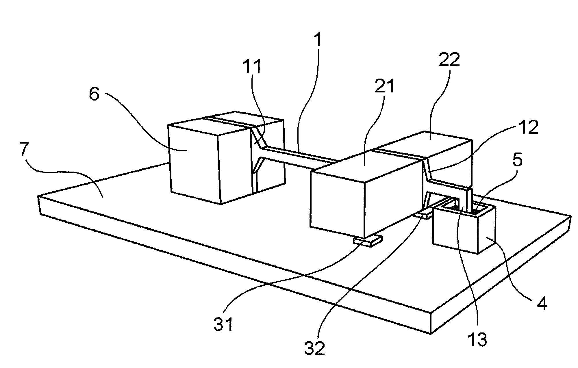
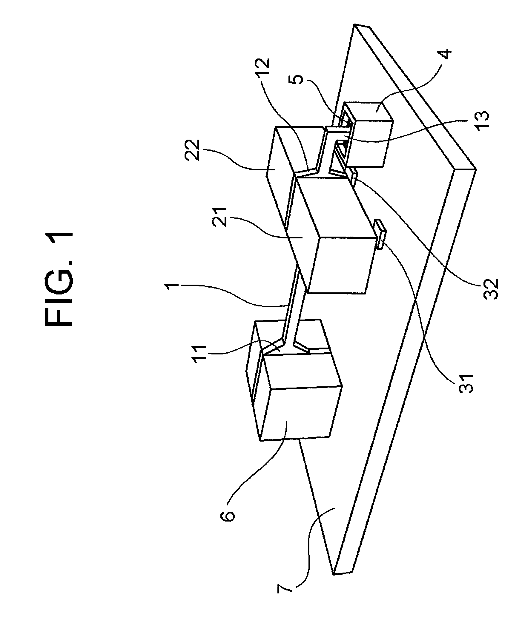
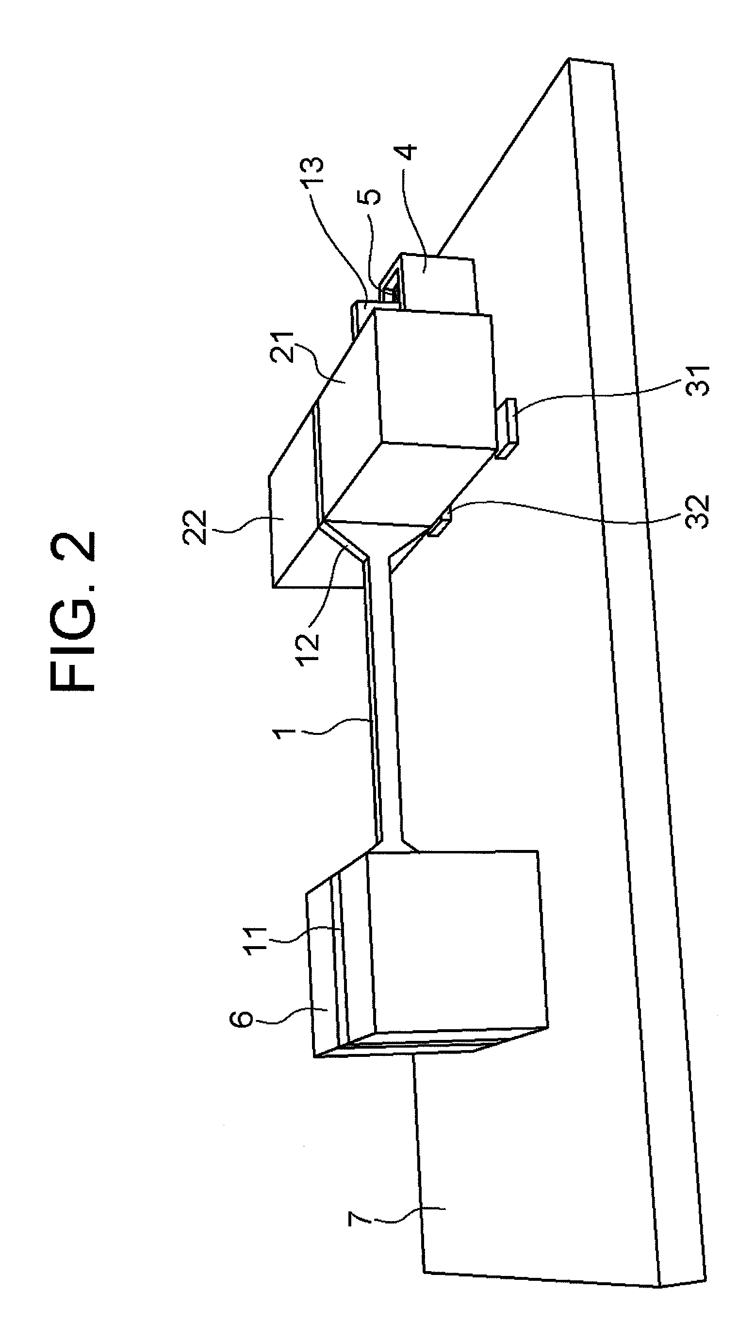
[0045]First, FIG. 1 is an illustration of the tilt angle sensor of the first embodiment viewed obliquely from the top end side, and FIG. 2 is an illustration thereof viewed obliquely from the rear end side. FIG. 3 is an illustration of the tilt angle sensor viewed from the above, and FIG. 4 is an illustration thereof viewed from the side. Further, FIG. 5 is a detailed illustration showing each disassembled part of the tilt angle sensor.

[0046]As shown in those illustrations, the tilt angle sensor comprises a mount base 7 for loading each structural elements, a supporting block 6 fixed on the mount bas...

second embodiment

[0063]Next, a second embodiment of the present invention will be described by referring to FIG. 9-FIG. 10. FIG. 9 is an illustration of a tilt angle sensor according to the second embodiment viewed obliquely from the front, and FIG. 10 is an illustration thereof viewed almost from the straightforward direction.

[0064]The tilt angle sensor according to the second embodiment employs almost the same constitution as the one disclosed in the above-described first embodiment, except for the structure of a dash pod 104. As shown in FIG. 9 and FIG. 10, the dash pod 104 according to the second embodiment has two plate-like parts extended upwards in parallel, and it is formed to open upwardly in substantially U-letter form. A gel 105 having a prescribed viscosity is filled between the two plate-like parts. The gel 105 is housed by being remained within the U-letter part of the dash pod 104 because of the viscosity. The lower end part of the bent part 13 that is a part of the suspension 1 is di...

third embodiment

[0066]Next, a third embodiment of the present invention will be described by referring to FIG. 11-FIG. 12. FIG. 11 is an illustration of a tilt angle sensor according to the third embodiment viewed obliquely from the front, and FIG. 12 is an illustration thereof viewed almost from the straightforward direction.

[0067]The tilt angle sensor according to the third embodiment employs almost the same constitution as the one disclosed in the above-described second embodiment, except for the shape of the tip part of the suspension 1. A dash pod 204 according to the third embodiment has two plate-like parts extended upwards in parallel, and it is formed to open upwardly in substantially U-letter form, as in the case of the second embodiment. The height of the two plate-like parts is set higher than the case of the second embodiment, and a gel 205 having a prescribed viscosity is filled therebetween.

[0068]A far end part 213 of the suspension 1 according to this embodiment is not bent downward...


PUM


Abstract

To provide a tilt angle sensor that is capable of detecting acceleration, a tilt angle, and the like of a device to which the tilt sensor angle is mounted, and also capable of reducing the size and the cost with a simple structure. The tilt angle sensor comprises: a spring member having a fixed end a free end that has a flexibility to be bent at least in one direction; a magnetic field generating device for generating a magnetic field, which is mounted at the free end of the spring member; a magnetic field detecting device provided by facing the magnetic field generating device for detecting a direction of the magnetic field generated by the magnetic field generating device; and a damping device for giving a damping force to a bending action of the spring member.

Description

BACKGROUND OF THE INVENTION[0001]1. Field of the Invention[0002]The present invention relates to a tilt angle sensor and, more specifically, to a tilt angle sensor that is capable of measuring a tilt angle, acceleration, and the like at least in one direction.[0003]2. Description of the Related Art[0004]In order to detect an action and a tilt of a prescribed object, it has conventionally been investigated to utilize an acceleration sensor that detects the acceleration of the object. For example, the acceleration sensor can be utilized to: detect a tilt to find out whether or not a camera is being held properly at the time of pressing a shutter release; detect a tilt of a motorbike for preventing it from falling down; detect a tilt of an electronic equipment, which indicates the loaded state, e.g., whether or not it is placed horizontally; and so on. Further, the acceleration sensor can also be utilized to detect forcible shifting or falling of an electronic equipment instantly so as...

Claims


Application Information

Patent Timeline
Patent Type & Authority Applications(United States)
IPC IPC(8): G01B7/30
CPCB82Y25/00G01C9/06G01R33/091G01P15/105G01R33/0385G01C2009/064G01P2015/0828
Inventor KASAJIMA, TAMONNAKAJIMA, HIROYOSHIDONG, YONG JUNYU, FU
Owner SAE MAGNETICS (HK) LTD
Why Eureka
Try Eureka