Microscope
- Summary
- Abstract
- Description
- Claims
- Application Information
AI Technical Summary
Benefits of technology
Problems solved by technology
Method used
Image
Examples
embodiment 1
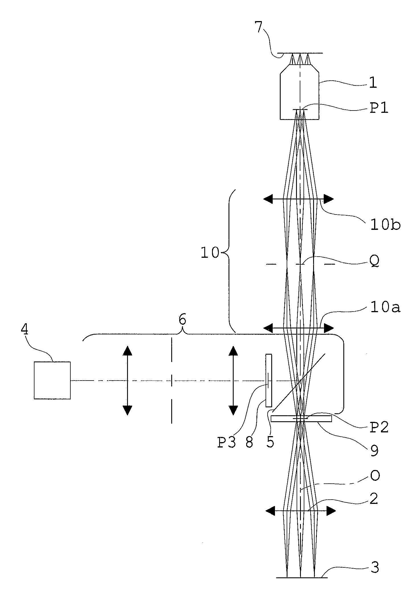
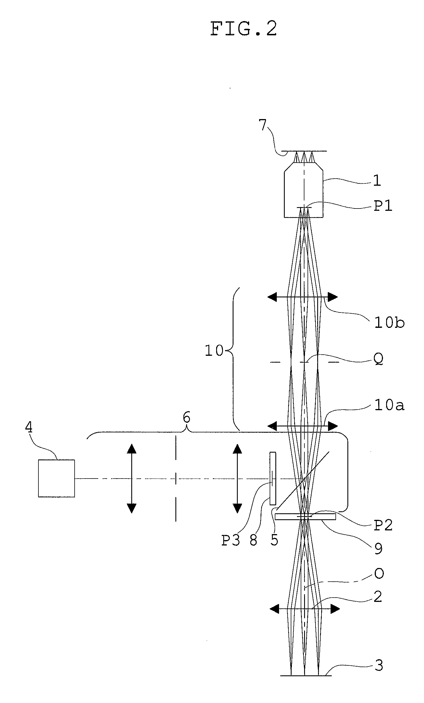
[0140]FIG. 4 is an explanatory view showing the arrangement of an illumination light source and a reflecting fluorescence illumination optical system in the microscope according to Embodiment 1 of the present invention. In the microscope of Embodiment 1, the illumination light source 4 (14) is constructed with a collection-type reflector light source 14a. The reflecting fluorescence illumination optical system 6 (16) includes a collector lens 16a, a fly-eye lens 16b, the excitation filter 8 (18), and the dichroic mirror 5 (15). Also, in FIG. 4, reference numeral 9 (19) represents the barrier filter. The reflector light source 14a is constructed with an arc light source, such as a mercury lamp or a metal halide lamp, provided with an elliptical reflector mirror 14a1. The elliptical reflector mirror 14a1 is constructed so that a convergent beam is emitted by reflection to form a primary light source image at a primary imaging position R1. The collector lens 16a is constructed so that ...
embodiment 2
[0146]FIG. 5 is an explanatory view showing the arrangement of an illumination light source and a reflecting fluorescence illumination optical system in the microscope according to Embodiment 2 of the present invention. In the microscope of Embodiment 2, the illumination light source 4 (14) is constructed with a parallel-beam-type reflector light source 14a′. The reflecting fluorescence illumination optical system 6 (16) includes an afocal system 16a′, the fly-eye lens 16b, the excitation filter 8 (18), and the dichroic mirror 5 (15). Also, in FIG. 5, reference numeral 9 (19) represents the barrier filter. The reflector light source 14a′ is constructed with an arc light source, such as a mercury lamp or a metal halide lamp, provided with an elliptical reflector mirror 14a1′. The elliptical reflector mirror 14a1′ is constructed so that a parallel beam is emitted by reflection.
[0147]The afocal system 16a′ is constructed so that the diameter of the parallel beam emitted from the reflec...
embodiment 3
[0151]FIG. 6 is an explanatory view showing the arrangement of an illumination light source and a reflecting fluorescence illumination optical system in the microscope according to Embodiment 3 of the present invention. In the microscope of Embodiment 3, the illumination light source 4 (14) is constructed with the parallel-beam-type reflector light source 14a′. The reflecting fluorescence illumination optical system 6 (16) includes an afocal system 16a″, the fly-eye lens 16b, the excitation filter 8 (18), and the dichroic mirror 5 (15). Also, in FIG. 6, reference numeral 9 (19) represents the barrier filter.
[0152]The reflector light source 14a′ is constructed with the arc light source, such as a mercury lamp or a metal halide lamp, provided with the elliptical reflector mirror 14a1′. The elliptical reflector mirror 14a1′ is constructed so that a parallel beam is emitted by reflection. The afocal system 16a″ is constructed so that the parallel beam emitted from the reflector light so...
PUM
 Abstract
Description
Claims
Application Information
 - R&D
- Intellectual Property
- Life Sciences
- Materials
- Tech Scout
- Unparalleled Data Quality
- Higher Quality Content
- 60% Fewer Hallucinations
Browse by: Latest US Patents, China's latest patents, Technical Efficacy Thesaurus, Application Domain, Technology Topic, Popular Technical Reports.
© 2025 PatSnap. All rights reserved.Legal|Privacy policy|Modern Slavery Act Transparency Statement|Sitemap|About US| Contact US: help@patsnap.com


