Heat sink

a heat sink and heat sink technology, applied in the direction of semiconductor/solid-state device details, lighting and heating apparatus, laminated elements, etc., can solve the problems of shortening the life of semiconductors, deteriorating the performance of devices, and possible breakage, so as to increase the heat dissipation performance of heat sinks and heat dissipation. the effect of large surface area and high heat dissipation performan

a heat sink and heat sink technology, applied in the direction of semiconductor/solid-state device details, lighting and heating apparatus, laminated elements, etc., can solve the problems of shortening the life of semiconductors, deteriorating the performance of devices, and possible breakage, so as to increase the heat dissipation performance of heat sinks and heat dissipation. the effect of large surface area and high heat dissipation performan

US20090195990A1Inactive Publication Date: 2009-08-06JISOUKEN CO LTD

Image

  • Heat sink
  • Heat sink
  • Heat sink

Examples


Embodiment Construction

[0113]Hereinafter, the present invention will be described in detail.

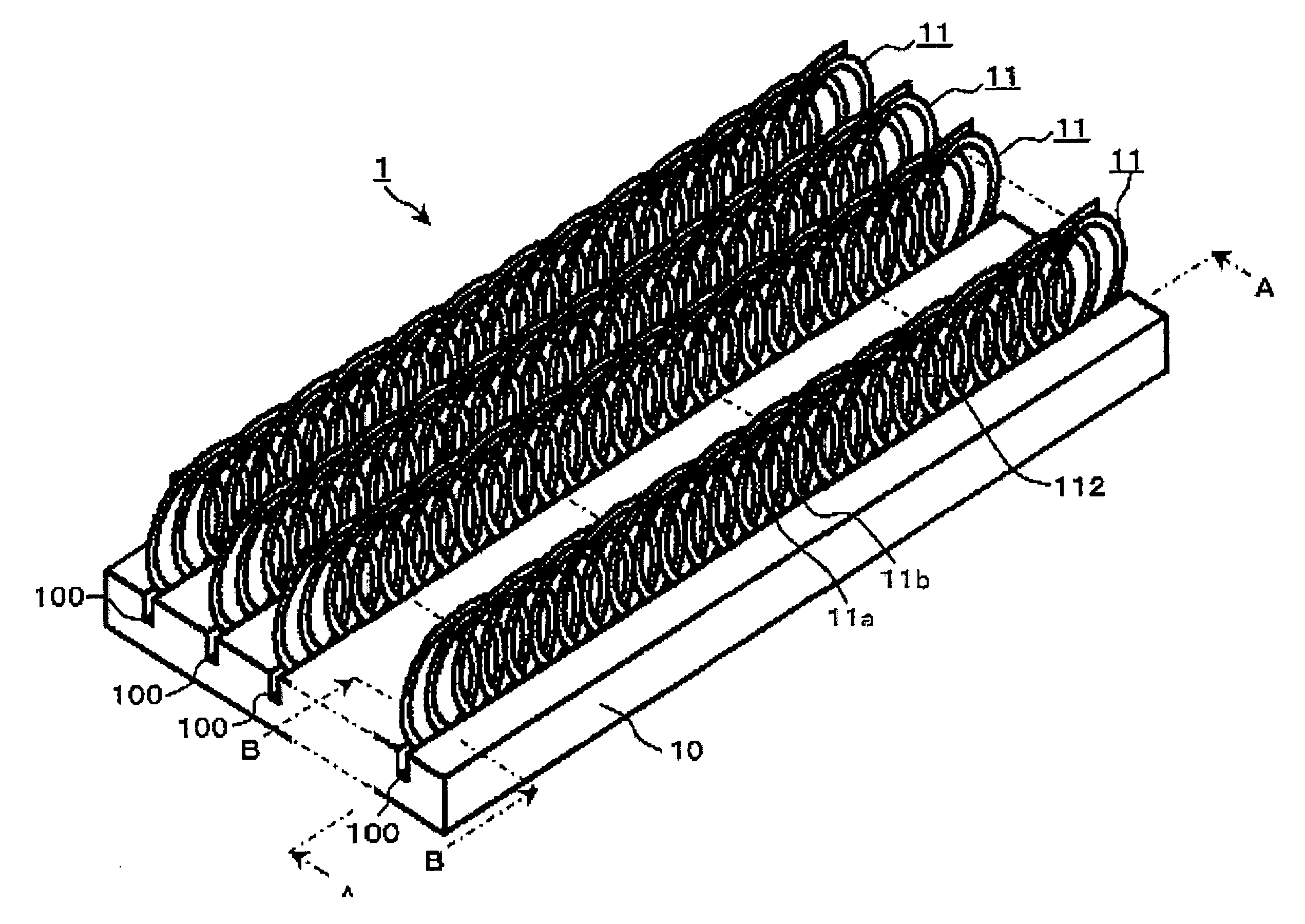
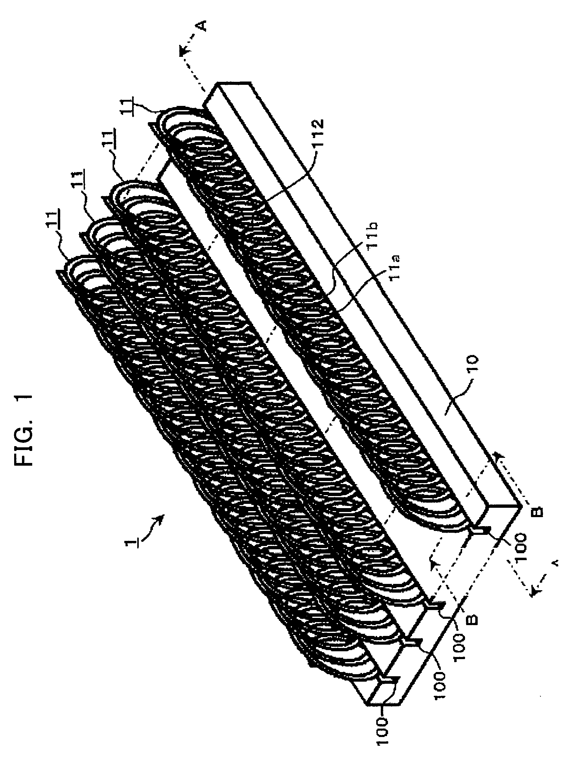
[0114]First, the first embodiment (1) of the invention will be described with reference to FIGS. 1 and 2. The heat sink in FIG. 1 generally comprises a base plate 10 with a plurality of grooves 100, and fins 11 formed of metal wire coil arranged along the grooves 100. In FIG. 1, only one row of fins 11 is illustrated and the other rows of fins are partially abbreviated for ease of explanation.

[0115]The fins 11 are formed by flattening the metal wire coil. Adjacent coil elements 11a and 11b are in close contact with each other at contact parts 113 through which heat diffuses rapidly throughout the fins 11. Thus, the metal wire is formed in a coil so as to provide a large surface area to the fins, thus increasing the heat dissipation performance.

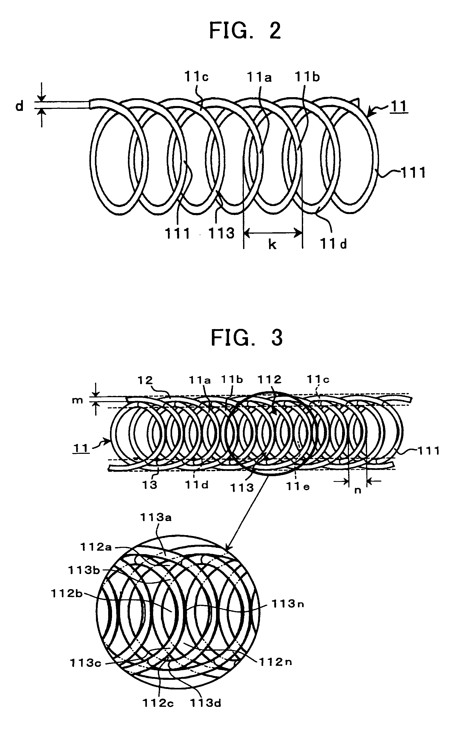
[0116]The fins 11 made of the metal wire coil as shown in FIG. 2 have end parts 11c and 11d of the flat surface 111 to increase the density of the coil elements. Consequently...


PUM


Abstract

The present invention seeks to provide a novel heat sink capable of being effectively produced at a low cost and having excellent heat dissipation performance. The heat sink comprises fins 11 of a metal wire coil formed of coil elements 11a and 11b made by winding a flat metal wire. The fins 11 are disposed on a heat conductive base plate 10 with flat surfaces 111 of the fins arranged perpendicular to the base plate 10.

Description

TECHNICAL FIELD[0001]This invention relates to a heat sink, and more specific, belongs to a technical field of the heat sink, which is mounted primarily on a semiconductor device to have flowing gas or liquid absorb heat generated within the semiconductor device, thereby to cool the semiconductor device or used as a heat exchange element for many applications.BACKGROUND OF THE ART[0002]Quantity of heat generated by a semiconductor device has been increasing with improvement of performance of the semiconductor device. The rise in temperature of the semiconductor device deteriorates the performance of the device. When a junction of the semiconductor is kept in a high temperature state, the semiconductor shortens its life by heat, and in the worst case, may possibly break. Such being the case, there has been used a heat sink for cooling the heat within the semiconductor device such as a CPU of a computer by diffusing the heat into cold air.[0003]A conventional heat sink improved the he...

Claims


Application Information

Patent Timeline
06 Aug 2009
Publication
US20090195990A1
IPC
H05K7/20; F28D1/00; F28F3/02; H01L23/367
CPC
F28F3/022; H01L23/3677; H01L2924/3011; H01L2924/0002; H01L2924/00; H01L23/36; H01L23/367
Inventors
HONMA, MITSUO