Multi-Fiber Optical Patch Cord Breakout Assembly

Inactive Publication Date: 2009-08-06
CABLES PLUS
View PDF34 Cites 88 Cited by
  • Summary
  • Abstract
  • Description
  • Claims
  • Application Information

AI Technical Summary

Benefits of technology

[0009]The present invention further relates to a fiber optic communication system. The system comprises a chassis. A cassette is housed within the chassis. The cassette has a fiber cable adapter. A fiber cable comprises a fiber optic connector connected to the fiber cable adapter. An integrated fiber cable management system comprises a fitting having a body with a collet through which the cable passes. A lock nut is threaded o

Problems solved by technology

Additionally, while demand for more bandwidth and more connections grows, the cost for space allocated to data communications increases, creating a clash between adding more connections and cost.
In multi-fiber connectors, there is a problem with light separation between fibers at hi

Method used


Image

  • Multi-Fiber Optical Patch Cord Breakout Assembly
  • Multi-Fiber Optical Patch Cord Breakout Assembly
  • Multi-Fiber Optical Patch Cord Breakout Assembly

Examples


Example

[0026]Detailed reference will now be made to the drawings in which examples embodying the present invention are shown. The detailed description uses words and phrases as identifiers on the drawings. Like or similar designations in the drawings and description have been used to refer to like or similar parts of the invention. The following description is merely exemplary in nature and is not intended to limit the present invention, or its application or uses. It should be understood that throughout the drawings, corresponding reference numerals indicate like or corresponding parts and features.

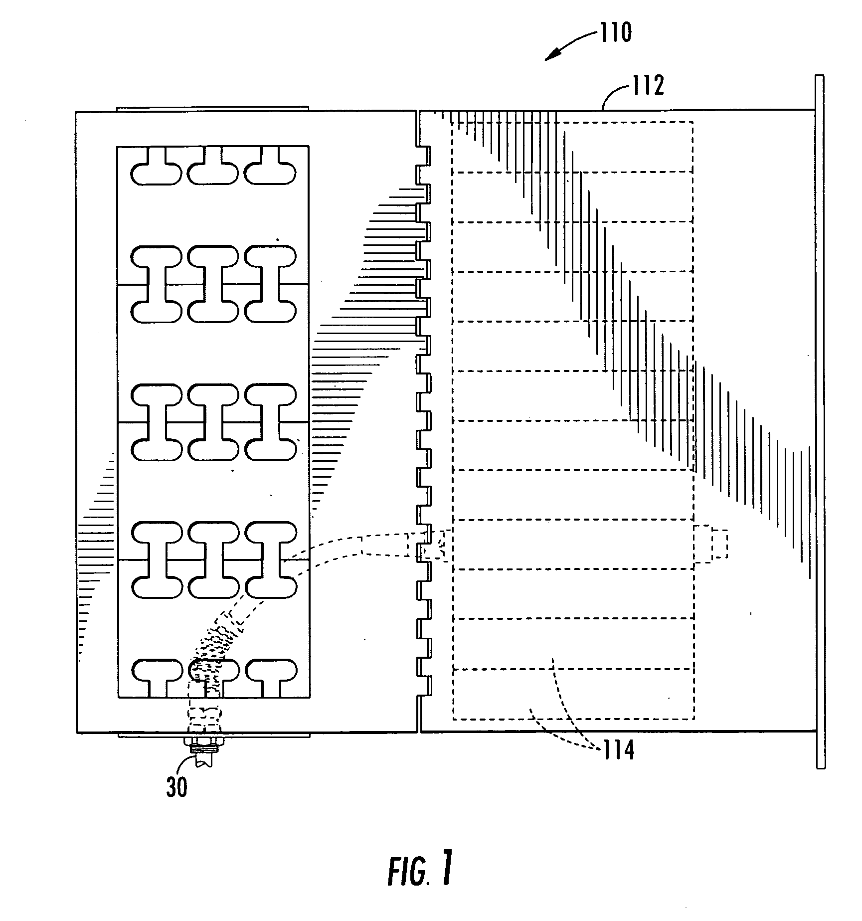
[0027]As shown generally in FIG. 1, a high-density fiber optic communication system 110 generally comprising a fiber chassis 112, cassettes 114 housed within the chassis 112, and a high-density fiber optic cable 30 connected to the cassette 114 via connectors, all of which will be described in further detail in the description that follows.

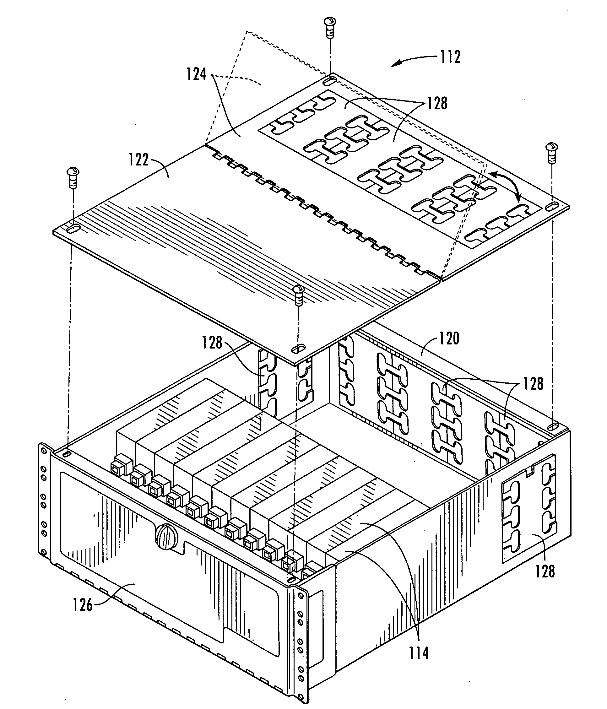
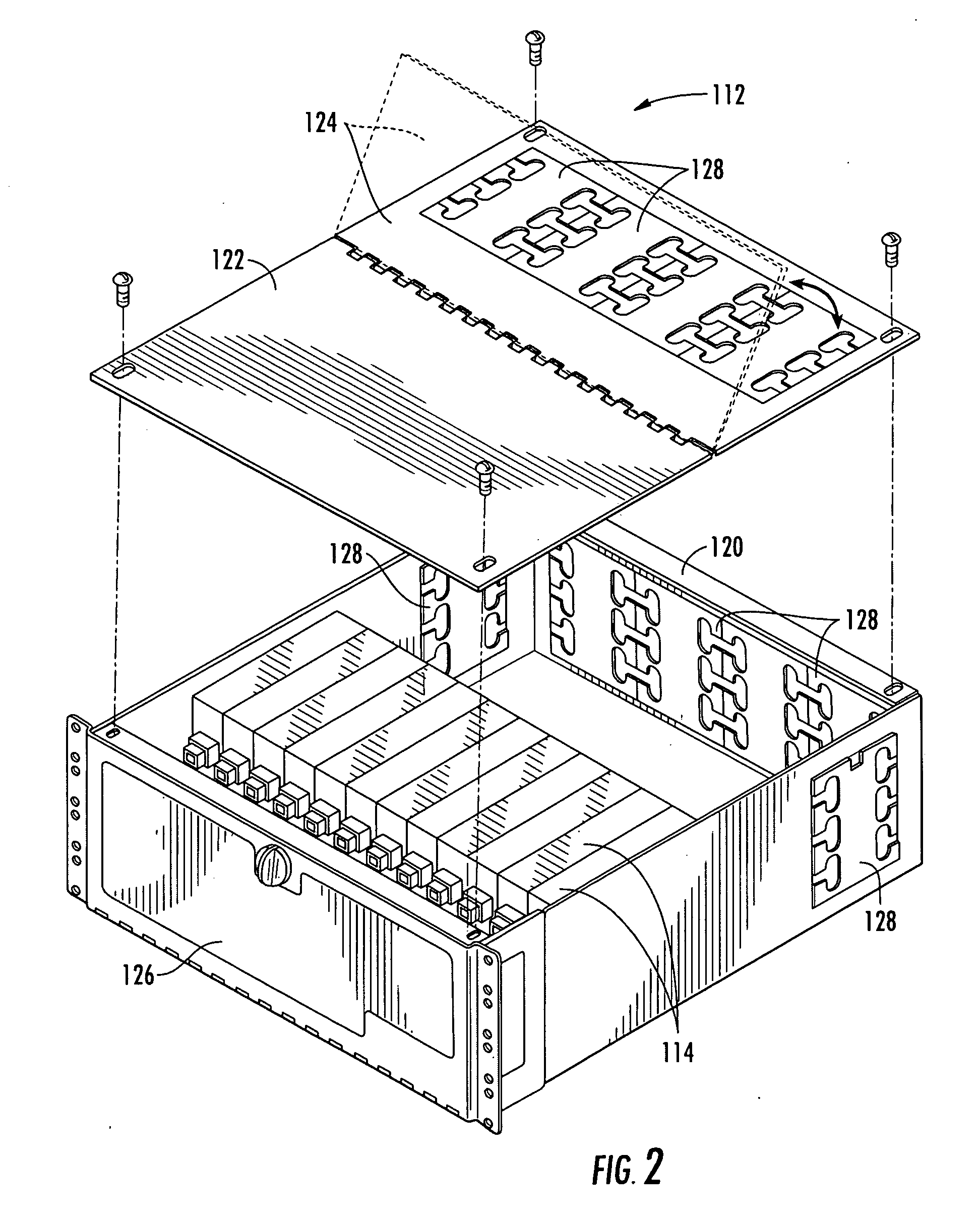
[0028]An exemplary chassis 112 is shown in FIG. 2. The ...


PUM


Abstract

A fiber cable adapter comprises adjacent rows of fibers, each beginning with a set of fibers comprising a fiber pair, which comprises a transmitting fiber adjacent a receiving fiber, and a spare fiber adjacent the fiber pair. The spare fiber immediately precedes the fiber pair in one of the rows and immediately proceeds the fiber pair in the other row. A fiber cable cassette comprises an adapter panel supporting the fiber cable adapter. An integrated fiber cable management system comprises a fitting having a body with a collet through which a cable passes. A lock nut is threaded on a first end of the body to hold the body in relation to a chassis. A sealing nut is threaded on a second end of the body to tighten the collet on the cable to hold the cable in place in relation to the chassis. A flexible protector extends from the sealing nut to control the bend of the cable between the chassis and a fiber cable cassette. The flexible protector restricts the bend of the cable and thus extends the life of the cable.

Description

CROSS-REFERENCE TO RELATED APPLICATIONS[0001]This application claims the benefit of U.S. Provisional Application No. 61 / 025,468 filed Feb. 1, 2008, the disclosure of which is incorporated herein by reference.BACKGROUND OF THE INVENTION[0002]The invention relates generally to optical communications and more particularly to fiber optic cables and connections used for connecting electronic equipment used in the transmission of digital and analog data.[0003]In the field of data communications, fiber optic cables have surpassed electric cables because of their enormous bandwidth capabilities. As technology grows and more demands are being placed on data transfer, the need for higher bandwidth and more connections is growing. Additionally, while demand for more bandwidth and more connections grows, the cost for space allocated to data communications increases, creating a clash between adding more connections and cost.[0004]Fiber optic cables used in data communications are terminated at e...

Claims


Application Information

Patent Timeline
IPC IPC(8): G02B6/00
CPCG02B6/4472G02B6/4453
Inventor MULLSTEFF, DAVID M.TAYLOR, JOHN P.GERVASONI, MARK A.
Owner CABLES PLUS
Why Eureka
Try Eureka