
Wind turbine blade with lightning receptor

Active Publication Date: 2009-08-06
GENERAL ELECTRIC CO
View PDF6 Cites 57 Cited by
  • Summary
  • Abstract
  • Description
  • Claims
  • Application Information

AI Technical Summary

Benefits of technology

[0010]An advantage of the present invention is that the installation of the common conductor wire for both receptors is safer because the common conductor wire is installed after the shells are removed from the molds.
[0011]Another advantage of the present invention is that the installation of the common conductor wire for both receptors is easier because the common conductor wire is installed through a port in the blade shell and not in an opening between the two shells before the shells are bonded.
[0012]Yet another advantage of the present invention is that a common conductor wire for both receptors is cheaper because only one conductor is used.
[0013]Still another advantage of the present invention is a more reliable lightening protection system exists because the common conductor wire is not exposed to the stresses of the shell during operation of the wind turbine.

Problems solved by technology

Since the wind turbine blades are so large and are disposed in open areas, they attract and are often hit by lightning.
The multiple conductor cables require each of the conductor cable to be disposed along the shells in high stress areas, leaving room for errors and failure.
However, access to the inside of the blade is limited after the shells are bonded, therefore it is difficult to connect the a receptor with one single conductor.
Often the installer must insert their arms through the two shells while they are still in the molds, exposing themselves to the danger of one of the heavy shells falling from the mold and causing harm to the installer.

Method used


Image

  • Wind turbine blade with lightning receptor
  • Wind turbine blade with lightning receptor
  • Wind turbine blade with lightning receptor

Examples


Embodiment Construction

[0021]The present invention now will be described more fully hereinafter with reference to the accompanying drawings, in which a preferred embodiment of the invention is shown. This invention may, however, be embodied in many different forms and should not be construed as limited to the embodiments set forth herein; rather, these embodiments are provided so that this disclosure will be thorough and complete and will fully convey the scope of the invention to those skilled in the art.

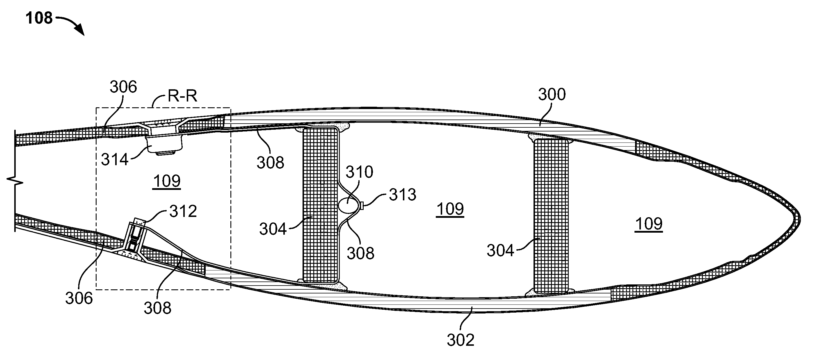
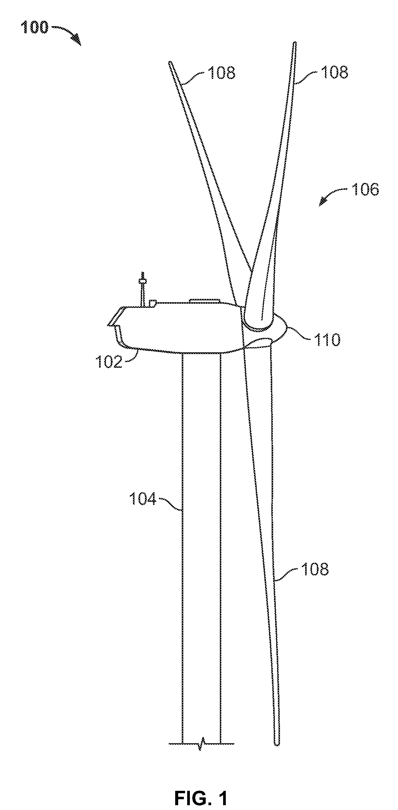
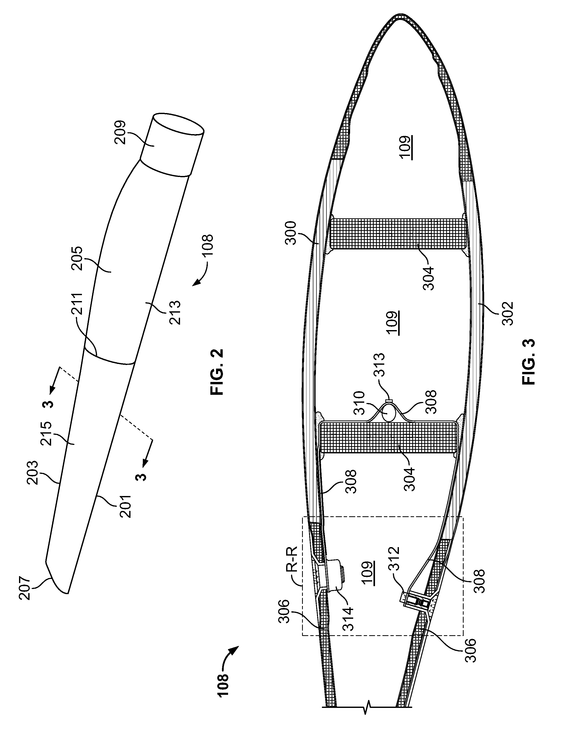
[0022]FIG. 1 shows a wind turbine 100 having a nacelle 102 housing a generator (not shown in FIG. 1). Nacelle 102 is a housing mounted atop a tower 104, only a portion of which is shown in FIG. 1. The height of tower 104 is selected based upon factors and conditions known in the art, and may extend to heights up to 60 meters or more. The wind turbine 100 may be installed on any terrain providing access to areas having desirable wind conditions. The terrain may vary greatly and may include, but is not lim...


PUM


Abstract

A wind turbine blade having two shell portions bonded together to form a wind turbine blade having an interior space having an axial length. A web disposed between the shell portions in the interior space and extending substantially the axial length thereof. Lightning receptors are disposed on the shell portions and a conductor is disposed in the interior space. The conductor is configured to contact the lightning receptors. One shell portion of the two shell portions has a removable section, e.g. a plug, receptor or panel, to provide access to the opposite conductor. A cable mounted on the web is configured to extend substantially the axial length of the wind turbine blade and is in electrical contact with the conductor.

Description

FIELD OF THE INVENTION[0001]The present invention relates generally to wind turbines. More specifically, the present invention relates to a wind turbine blade including a lightning receptor within the blade and access to the receptor in the turbine blade.BACKGROUND OF THE INVENTION[0002]It is known to provide wind turbine rotor blades with lightning protection systems to protect them from strokes of lightning. For example, a rotor blade may be provided with a lightning receptor of an electrically conductive material. The lightning receptor may capture a strike of lightning and conduct the current through a lightning conductor cable extending in the longitudinal direction of the blade to a ground in the tower.[0003]Generally, a wind turbine includes a plurality of blades coupled to a rotor through a hub. The rotor is mounted within a housing or nacelle, which is positioned on top of a tubular tower or base. Utility grade wind turbines (i.e. wind turbines designed to provide electrica...

Claims


Application Information

Patent Timeline
IPC IPC(8): F03D11/00
CPCF03D1/0675F03D11/0033Y02E10/722Y02E10/721F05B2240/302F03D80/30Y02E10/72
Inventor JACOBSEN, ERIC M.ALTHOFF, NICHOLAS K.STAM, RONALD EDUARDGANN, MATTHEW
Owner GENERAL ELECTRIC CO
Learn More