Battery assembly

a battery assembly and battery technology, applied in the field of battery assembly, can solve the problems of large installation space, complex wire routing, and thick battery assembly, and achieve the effects of reducing the total number of terminals, and reducing the thickness of the battery assembly

Inactive Publication Date: 2009-08-06
TOYOTA JIDOSHA KK
View PDF10 Cites 18 Cited by
  • Summary
  • Abstract
  • Description
  • Claims
  • Application Information

AI Technical Summary

Benefits of technology

[0005]The present invention was made in view of the foregoing and its object is to provide a battery assembly formed by connecting a plurality of secondary batteries in parallel with each other, ensuring sufficient distance between each of the terminals, allowing formation of a compact battery assembly itself, and allowing connection of wires to the terminals in a simple manner.
[0007]In the battery assembly in accordance with the present invention, secondary batteries adjacent to each other in the stacking direction share the first collector electrode. Therefore, total number of terminals can be reduced. Further, as the first terminal portion and the second terminal portion are staggered, wires can be routed easily by connecting the first wire to a portion of the first terminal portion not overlapped with the second terminal portion and by connecting the second wire to a portion of the second terminal portion not overlapping with the first terminal portion. Further, unit cells adjacent to each other in the stacking direction share the collector electrode, and therefore, thickness of the battery assembly can be reduced. Further, as the secondary battery is positioned between each of the terminal portions, contact of terminal portions with each other can be prevented.

Problems solved by technology

Further, as the insulating film is provided between each of the secondary batteries, the battery assembly becomes thick, requiring much space to install the battery assembly.
When a plurality of secondary batteries are connected in parallel with each other, it becomes necessary to connect wires to a plurality of terminals, and when each terminal is to be connected to a wire, routing of wires becomes very complicated.

Method used


Image

  • Battery assembly
  • Battery assembly
  • Battery assembly

Examples


Embodiment Construction

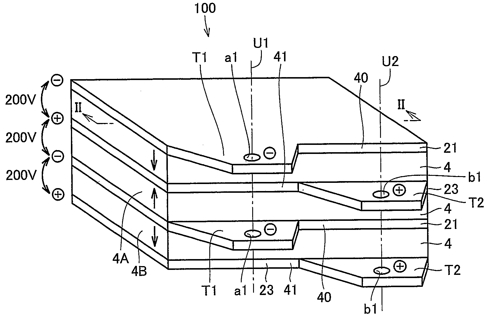
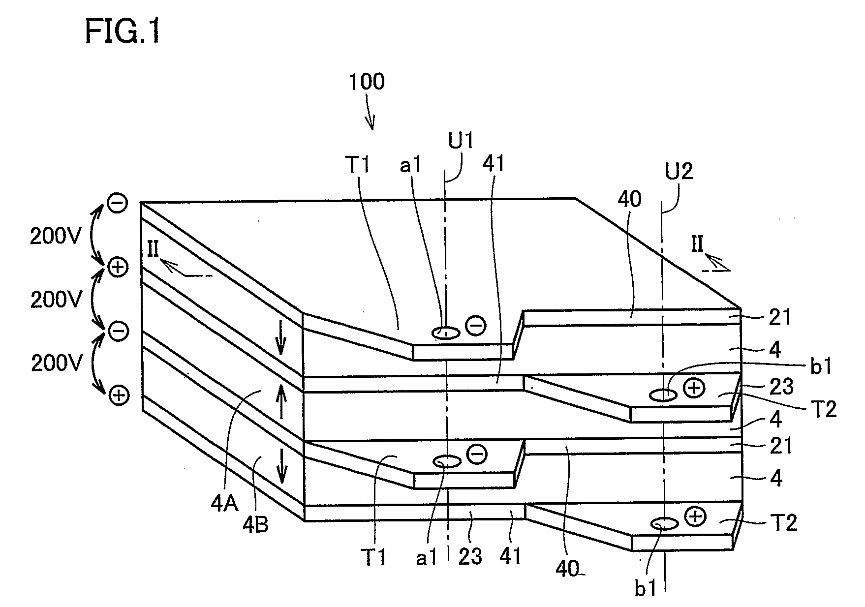
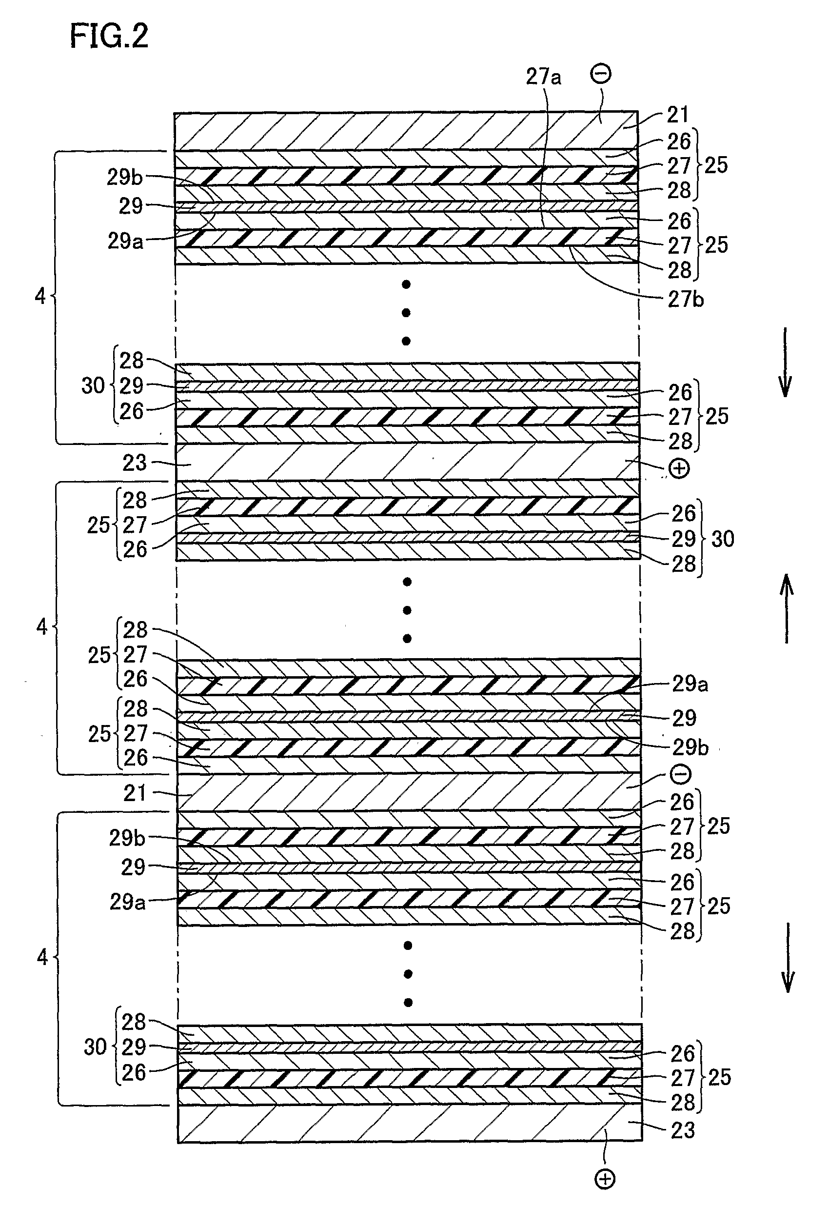
[0015]A battery assembly 100 in accordance with Embodiment 1 will be described with reference to FIGS. 1 to 7. FIG. 1 is a perspective view of battery assembly 100 in accordance with the embodiment, and FIG. 2 is a cross-sectional view taken along the line II-II of FIG. 1. Referring to FIG. 1, a plurality of bipolar secondary batteries (secondary batteries) 4, a plurality of plate-shaped negative collector electrodes (first collector plates) 21, and a plurality of plate-shaped positive collector electrodes (second collector plates) 23 are stacked to from the assembly.

[0016]Referring to FIG. 2, bipolar battery 4 is formed by successively stacking a plurality of electrode sheets (unit cells) 25 and collector foils 29 provided between each of the electrode sheets 25. The direction of stacking each electrode sheet 25 is the same as the direction of stacking bipolar secondary batteries 4, that is, the thickness direction of battery assembly 100.

[0017]Electrode sheet 25 includes an electr...


PUM

PropertyMeasurementUnit
polaraaaaaaaaaa
polarityaaaaaaaaaa
thickaaaaaaaaaa

Abstract

A battery assembly includes a plate shaped first collector electrode provided between first and second secondary batteries for electrically connecting the first and second secondary batteries; a second collector electrode of a polarity different from the first collector electrode, provided on a surface opposite to the surface of the first secondary battery on which the first collector electrode is provided; a first terminal portion provided at the first collector electrode and connected to a first conductive member; and a second terminal portion provided at the second collector electrode and connected to a second conductive member; wherein the first and second terminal portions are arranged staggered in a direction of stacking.

Description

TECHNICAL FIELD[0001]The present invention relates to a battery assembly formed by stacking a plurality of unit cells.BACKGROUND ART[0002]Conventionally, various types of secondary batteries formed by stacking a plurality of battery cells in series have been proposed, for example, in Japanese Patent Laying-Open Nos. 2000-311718, 2004-171954 and 2005-011658. Such a secondary battery has collector electrodes provided at opposite ends, and a terminal to be connected to a wire is provided at the collector electrode.[0003]In order to connect a plurality of secondary batteries structured as described above in parallel with each other, a method may be possible to stack the plurality of secondary batteries with an insulating film interposed, so that terminals are connected in parallel with each other.[0004]When the secondary batteries are stacked in the manner mentioned above, however, the terminals of adjacent secondary batteries come close to each other with the insulating film posed ther...

Claims


Application Information

Patent Timeline
Patent Type & Authority Applications(United States)
IPC IPC(8): H01M2/26H01M50/502H01M50/528H01M50/55H01M50/553
CPCH01M2/206H01M2/30H01M6/48Y02T10/7011H01M10/0418H01M10/052H01M10/4207H01M10/0413Y02E60/10H01M50/502Y02P70/50H01M50/553H01M50/55H01M50/50
Inventor NAKAMURA, YOSHIYUKI
Owner TOYOTA JIDOSHA KK
Why Eureka
Try Eureka