Premix Burner Control System and Method

Inactive Publication Date: 2009-08-06
MAXITROL
View PDF10 Cites 37 Cited by
  • Summary
  • Abstract
  • Description
  • Claims
  • Application Information

AI Technical Summary

Benefits of technology

[0008]The present invention discloses a method of maintaining flow of an air/fuel mixture to a burner. The burner is fed from a premix chamber enclosing a variable speed fan. The premix chamber also defines an air inlet, a fuel inlet, and an outlet in fluidic communication with the burner. The method includes the step of regulating a flow of gaseous fuel though the fuel inlet with a regulating control valve to maintain a specified pressure. The gaseous fuel and air are drawn into the premix chamber by operation of the fan. Mixture of the gaseous fuel and the air in the premix chamber are affected by operation of the fan to produce an air/fuel mixture. The air/fuel mixture is forced to the outlet by operation of the fan. The method continues with the step of lowering an inlet air pressure of air drawn through the air inlet by reducing the area of an air duct ahead of the air inlet to decrease the flow rate of the air/fuel mixture.
[0009]The present invention also discloses a premix burner control system. The system includes a housing defining a gas inlet for receiving a gaseous fuel, an air inlet for receiving air, and at least one outlet for connection to a burner. A fan is disposed in the housing for drawing the gaseous f

Problems solved by technology

However, typical methods of controlling the air/fuel mixture limit minimum firing rates of the burner due to their inability to maintain the desired air/fuel mixtures at very low fan pressures.
That is, the controls are not sensitive enough to react to minute changes in pressure that occur at reduced flow rates.
Ev

Method used


Image

  • Premix Burner Control System and Method
  • Premix Burner Control System and Method

Examples


Embodiment Construction

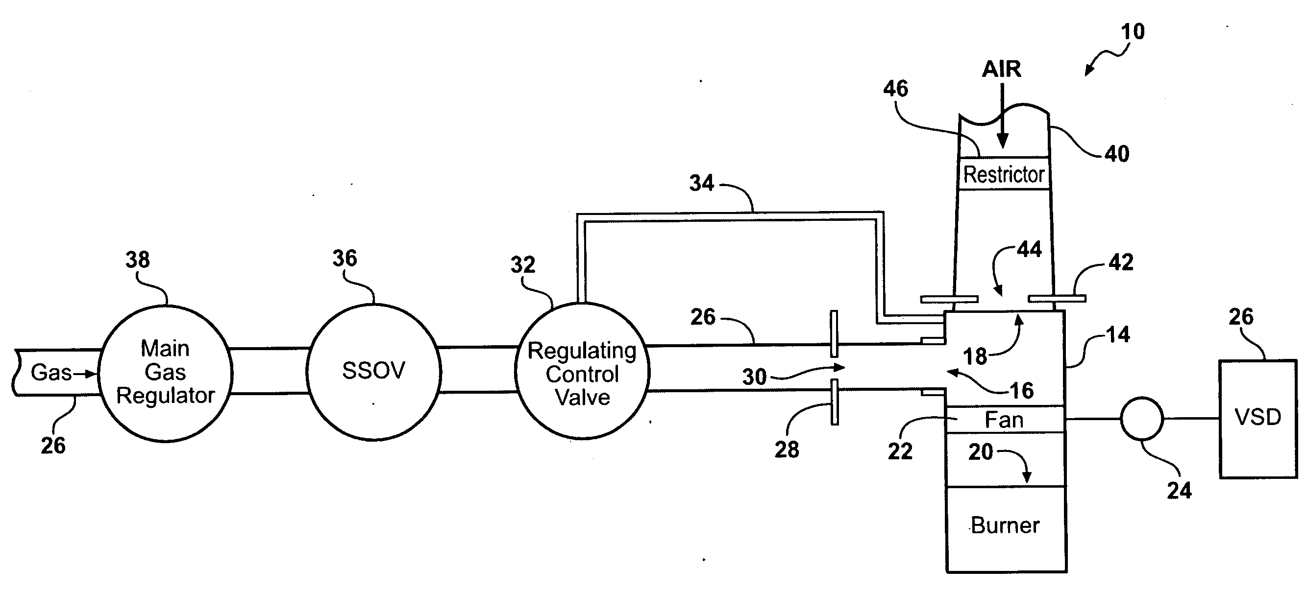
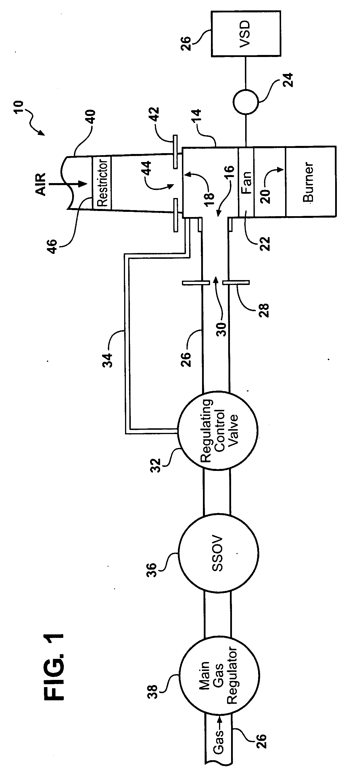
[0013]Referring to the Figures, wherein like numerals indicate like parts throughout the several views, a premix burner control system 10 and method of maintaining flow of an air / fuel mixture to a burner 12 is described herein.

[0014]Referring to FIG. 1, the premix burner control system 10 (hereafter referred to simply as the system 10) includes a housing 14 for mixing a gaseous fuel and air to produce an air / fuel mixture. Accordingly, the housing 14 defines a gas inlet 16 for receiving the gaseous fuel and an air inlet 18 for receiving air. The gaseous fuel may be natural gas; however, other suitable gaseous fuels may alternatively be utilized. The housing 14 may also be referred to as a pre-mix chamber by those skilled in the art.

[0015]The housing 14 also defines at least one outlet 20 for connection to the burner 12. The burner 12 preferably defines a plurality of burner ports (not shown) as is well known those skilled in the art. The air / fuel mixture is ignited and burned via the...


PUM


Abstract

A fan modulated premix burner control system includes a regulating control valve for regulating the pressure of gas fed to a premix chamber. The pressure of the gas is based on the pressure of air also fed into the chamber to produce a constant air/fuel ratio. The system also includes an air restrictor for reducing the pressure of the air to permit operation of the burner at low fan speeds.

Description

CROSS REFERENCE TO RELATED APPLICATION[0001]This application claims the benefit of provisional patent application No. 61 / 026,041, filed Feb. 4, 2008, which is hereby incorporated by reference.BACKGROUND OF THE INVENTION[0002]1. Field of the Invention[0003]The present invention relates generally to gas burners. More specifically, the present invention relates to a control system for premix gas burners and a method for maintaining flow of an air / fuel mixture to the premix gas burner.[0004]2. Description of the Related Art[0005]Premix gas burners operate by mixing gaseous fuel and air prior to produce an air / fuel mixture. The air / fuel mixture then enters the burner and is ignited and burned. A fan is often used to induce mixing of the air and fuel.[0006]However, typical methods of controlling the air / fuel mixture limit minimum firing rates of the burner due to their inability to maintain the desired air / fuel mixtures at very low fan pressures. That is, the controls are not sensitive en...

Claims


Application Information

Patent Timeline
IPC IPC(8): F23N1/02
CPCF23N1/022F23N2033/08F23N2025/04F23N2225/04F23N2233/08
Inventor MASEN, MARK
Owner MAXITROL
Why Eureka
Try Eureka