Ultrasonic diagnostic apparatus, diagnostic imaging apparatus, and program

a diagnostic apparatus and ultrasonic technology, applied in the field of ultrasonic diagnostic apparatus, diagnostic imaging apparatus, program, can solve the problems of difficult observation of a wide area including a concerned area, whole organ, etc., and achieve the effect of high speed

Inactive Publication Date: 2009-08-06
TOSHIBA MEDICAL SYST CORP
View PDF10 Cites 51 Cited by
  • Summary
  • Abstract
  • Description
  • Claims
  • Application Information

AI Technical Summary

Benefits of technology

[0014]The invention has been made in the above circumstances. Accordingly, it is an object of the invention to provide an ultrasonic diagnostic apparatus, a diagnostic imaging apparatus, and a program, which are configured to acquire and display three-dimensional images showing clearly a whole organ at high speed without limiting an echo window, even in an area including a fast-working organ like a heart, in the organ or in an area close to the organ.

Problems solved by technology

However, an ultrasonic diagnostic apparatus has following problems.
For an ultrasonic diagnostic apparatus, it is difficult to observe a wide area including a concerned area, for example, a whole organ such as a heart.
Further, in a heart and an area close to a heart, there are obstacles hard to transmit ultrasonic waves.
Therefore, when a heart is observed by an ultrasonic diagnostic apparatus, an echo window observable by using ultrasonic waves is limited by the lungs and ribs surrounding the heart, and it is very difficult to observe the whole heart from an echo window at one location.
Namely, an ultrasonic diagnostic apparatus is difficult to acquire and display sectional diagnostic images clearly showing a whole heart of a patient.
Such ultrasonic inspection of a heart requires various inspection techniques, and much time is required to master the techniques.
The ultrasonic inspection itself requires long time.
However, when three-dimensional images of a heat obtained by an ultrasonic diagnostic apparatus and a CT scanner, for example, a acquirable / displayable area is limited in a three-dimensional image obtained by an ultrasonic diagnostic apparatus, and it is difficult to find an image showing the same area as that in a three-dimensional image obtained by a CT scanner.
Further, even when three-dimensional images obtained by an ultrasonic diagnostic apparatus are displayed side by side, each display area is limited, and it is difficult to compare the images.
However, according to the technique disclosed in the Jpn. Pat. Appln. KOKAI Publication No. 2006-122657, though a two-dimensional array probe improved to have a shape easy to insert into a clearance between ribs of a patient, the specialized shape makes it difficult to manufacture the probe itself.
Further, the technique disclosed in the Jpn. Pat. Appln. KOKAI Publication No. 2006-122657 is not a technique to enable improvement of picture quality by an ultrasonic wave radiation angle or depth, and does not absolutely solve the above problem.

Method used


Image

  • Ultrasonic diagnostic apparatus, diagnostic imaging apparatus, and program
  • Ultrasonic diagnostic apparatus, diagnostic imaging apparatus, and program
  • Ultrasonic diagnostic apparatus, diagnostic imaging apparatus, and program

Examples


Embodiment Construction

[0032]An embodiment of the invention will be explained hereinafter with reference to the accompanying drawings.

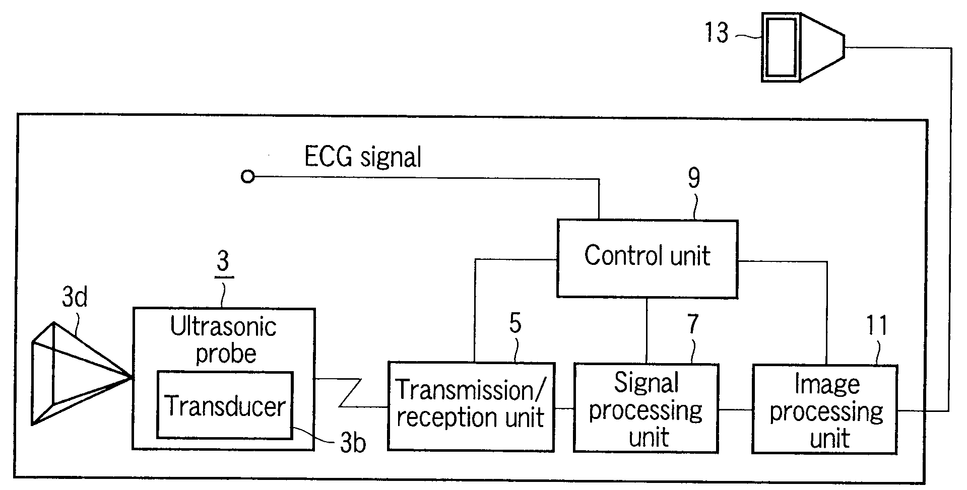
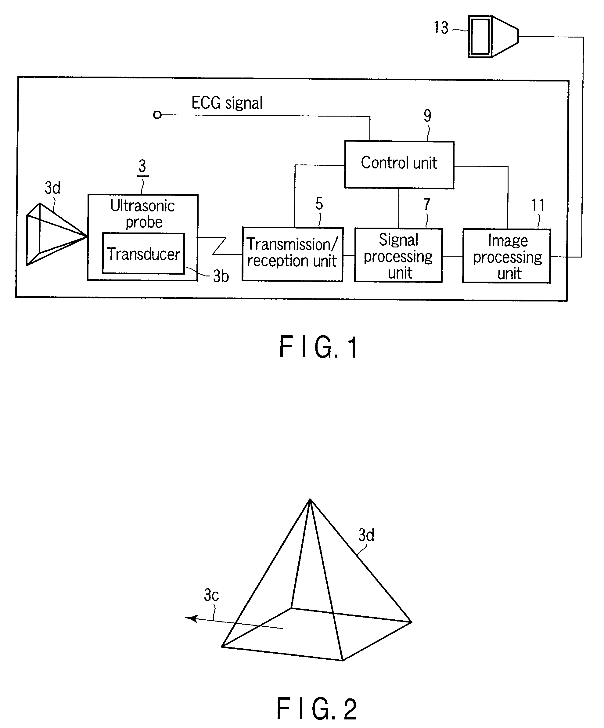
[0033]FIG. 1 is a diagram showing an example of configuration of an ultrasonic diagnostic apparatus according to this embodiment. As shown in the drawing, an ultrasonic diagnostic apparatus 1 comprises an ultrasonic probe 3, a transmission / reception unit 5, a signal processing unit 7, a control unit 9, and an image processing unit 11. Image data output from the image processing unit 11 is displayed on a display 13.

[0034]The ultrasonic probe 3 has a transducer 3b for transmitting and receiving ultrasonic waves. For example, as shown in FIG. 2, a two-dimensional scanning line from the ultrasonic probe 3 is moved in the direction of the arrow 3c, thereby forming a three-dimensional scanning space area 3d.

[0035]The transmission / reception unit 5 includes a transmission circuit, a receiving circuit, and an analog-to-digital conversion circuit.

[0036]The transmission circuit gener...


PUM


Abstract

An ultrasonic diagnostic apparatus is configured as follows. Namely, an ultrasonic diagnostic apparatus is provided with a control unit which collets a heart synchronized signal, etc. synchronizing with workings of a heart of a patient, etc., and an image processing unit which detects an overlapped area of the three-dimensional data acquired by ultrasonic scanning from different echo windows, for the three dimensional image data group acquired in the same time phase in synchronization with the heart synchronized signal or aspiration synchronized signal, combines the three-dimensional image data, and generates a panorama three-dimensional image data group consisting of panorama three-dimensional image data which are continued in time and have a display area larger than each of the three-dimensional image data.

Description

CROSS-REFERENCE TO RELATED APPLICATIONS[0001]This application is based upon and claims the benefit of priority from prior Japanese Patent Application No. 2008-021854, filed Jan. 31, 2008, the entire contents of which are incorporated herein by reference.BACKGROUND OF THE INVENTION[0002]1. Field of the Invention[0003]The present invention relates to an ultrasonic diagnostic apparatus, a diagnostic imaging apparatus, and a program for diagnosis by imaging internal organs of a patient. In particular, the present invention relates to an ultrasonic diagnostic apparatus, a diagnostic imaging apparatus, and a program, which form three-dimensional images of internal organs of a patient, and display the three-dimensional images by using ultrasonic waves.[0004]2. Description of the Related Art[0005]An ultrasonic diagnostic apparatus enables real-time observation of sectional images of a patient. In recent years, an ultrasonic diagnostic apparatus capable of acquiring and displaying three-dime...

Claims


Application Information

Patent Timeline
Patent Type & Authority Applications(United States)
IPC IPC(8): A61B8/14
CPCA61B8/0883A61B8/14A61B8/483A61B8/5253A61B8/5246A61B8/5238A61B8/543
Inventor HASHIMOTO, SHINICHIMINE, YOSHITAKAKIHARA, TOMOHIKOSHIKI, EIICHI
Owner TOSHIBA MEDICAL SYST CORP
Why Eureka
Try Eureka