System and method for efficient and optimal minimum area retiming

a technology minimum area, applied in the field of efficient and optimal retiming of minimum area, can solve the problems of high complexity, flow networks could still be very dense compared to the original circuit graph, and circuit graphs are usually expensive on large problems, so as to achieve efficient and optimal

Inactive Publication Date: 2009-08-06
NORTHWESTERN UNIV
View PDF19 Cites 2 Cited by
  • Summary
  • Abstract
  • Description
  • Claims
  • Application Information

AI Technical Summary

Benefits of technology

[0008]In accordance with the present invention the disadvantages of prior retiming methods has been overcome. The method of retiming registers or flip flops in a circuit design in accordance with the present invention performs minimum area retiming to relocate the registers / flip flops in a circuit design in an efficient and optimal manner.
[0009]More particularly, the method of the present invention dynamically generates constraints; maintains the constraints as a regular forest; and incrementally relocates registers in the circuit to reduce the register area in the circuit and / or the number of registers in the circuit.

Problems solved by technology

Therefore, the min-area retiming problem is more important for sequential circuit design, but of higher complexity.
Even though polynomially solvable, min-cost network flow computation, such as described in R. K. Ahuja, T. L. Magnanti, and J. B. Orlin “Network Flows: Theory, Algorithms, and Application,”Prentice Hall (1993), over a dense circuit graph is usually expensive on large problems.
However, even with these pruning techniques, as experimental results indicate, the flow networks could still be very dense compared to the original circuit graphs.
However, since only those moves that are better in cost and feasible in timing are allowed, these approaches are heuristic and may end up with a suboptimal solution.

Method used


Image

  • System and method for efficient and optimal minimum area retiming
  • System and method for efficient and optimal minimum area retiming
  • System and method for efficient and optimal minimum area retiming

Examples


Embodiment Construction

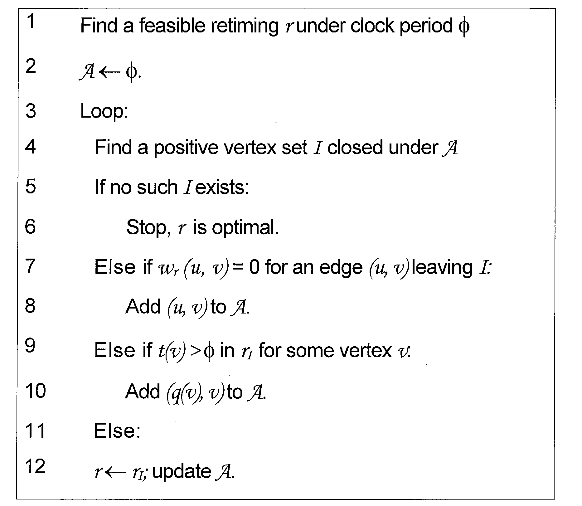
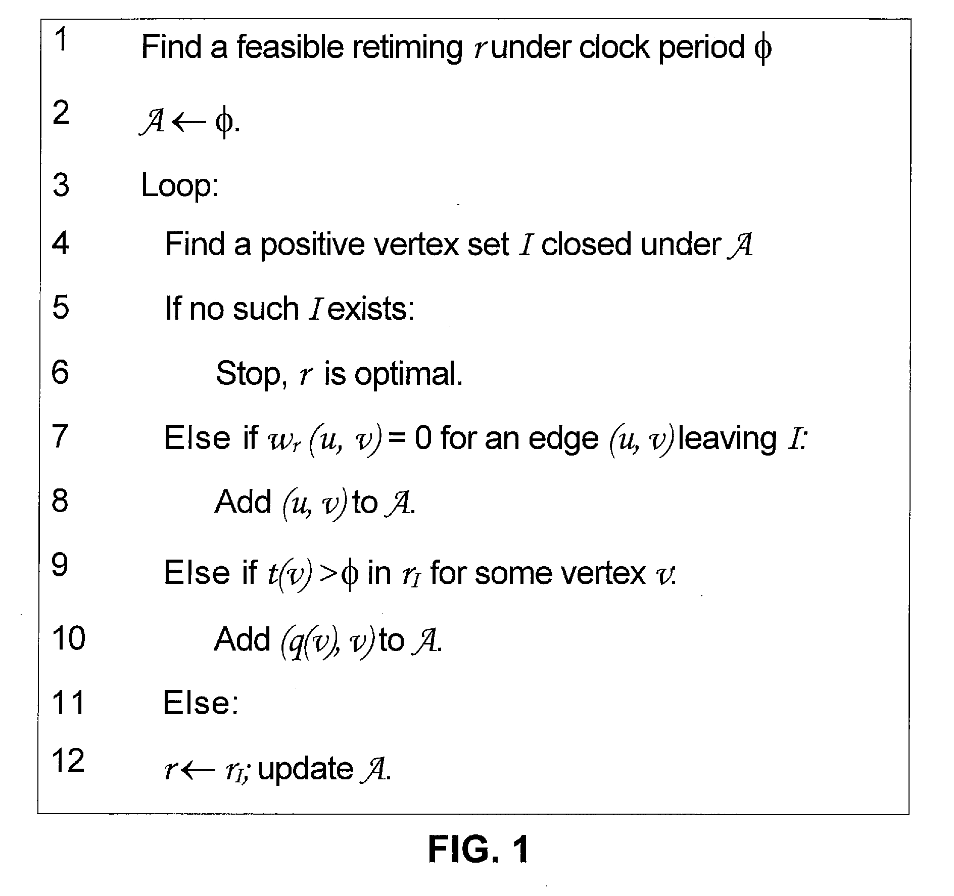
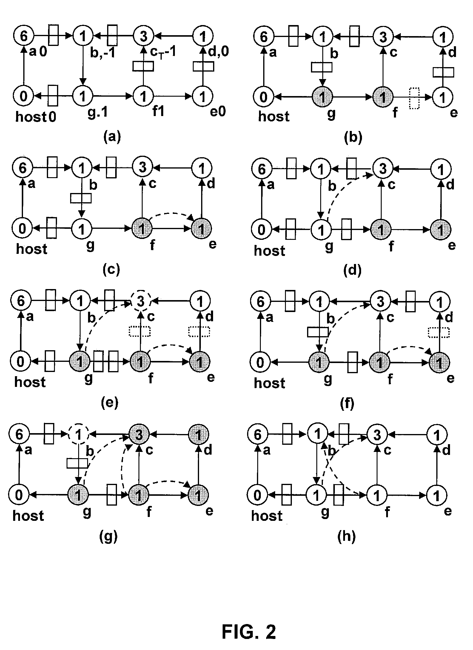
[0020]A synchronous sequential circuit is modeled by a directed graph G=(V,E) whose vertices V represent combinational gates and whose edges E represent signals between vertices. Nonnegative gate delays are given as vertex weights d: V→R* and the nonnegative numbers of FFs on the signals are given as edge weights w′: E→N. Given such a graph, the min-area retiming problem asks for an FF relocation w′: E→N such that the total FF area in the circuit is minimized while it works under a given clock period φ.

[0021]Conventionally, to guarantee that w′ is a relocation of w, a retiming is given by a vertex labeling r: V→Z representing the number of FFs moved backward over each gate from fanouts to fanins. Given r, the FF number on the edge (u, v) after retiming is wr(u,v)=w(u,v)+r(v)−r(u). A retiming r is valid if the FF number of every edge is nonnegative,

P0(r):(∀(u,v)∈E: wr(u, v)≧0)

[0022]For a circuit to work under a given clock period φ, the maximum combinational path delay in the circuit...


PUM


Abstract

A method for use in electronic design software efficiently and optimally produces minimized or reduced register flip flop area or number of registers / flip flops in a VLSI circuit design without changing circuit timing or functionality. The method dynamically generates constraints; maintains the generated constraints as a regular tree; and incrementally relocates registers / flip flops and / or the number of registers / flip flops in the circuit design.

Description

CROSS-REFERENCE TO RELATED APPLICATIONS / INCORPORATION BY REFERENCE[0001]This patent application makes reference to, claims priority to and claims benefit from U.S. Provisional Patent Application Ser. No. 61 / 025,548 filed on Feb. 1, 2008. The above stated provisional application is hereby incorporated herein by reference in its entirety.STATEMENT REGARDING FEDERALLY SPONSORED RESEARCH OR DEVELOPMENT[0002]This work was supported by the National Science Foundation (NSF) Grant No. CCR-0238484.FIELD OF THE INVENTION[0003]The present invention relates to a system and method for use in electronic design software to perform minimum area retiming to relocate registers or flip-flops in a circuit design through sequential transformation wherein circuit functionality is preserved and more particularly to such a retiming system and method that is optimal, efficient and minimizes memory usage.BACKGROUND OF THE INVENTION[0004]Retiming is one of the most powerful sequential transformations that rel...

Claims


Application Information

Patent Timeline
Patent Type & Authority Applications(United States)
IPC IPC(8): G06F17/50
CPCG06F17/5031G06F2217/84G06F17/505G06F30/3312G06F30/327G06F2119/12
Inventor ZHOU, HAIWANG, JIA
Owner NORTHWESTERN UNIV
Why Eureka
Try Eureka