Metal lathe, core drill adaptor and rate of cut device for use with a standard drill press

a core drill adaptor and drill press technology, applied in the direction of boring/drilling components, turning machine accessories, manufacturing tools, etc., can solve the problem that the steel is very difficult to drill or lathe, and achieve the effect of improving safety, durability, and cost-effective machining and lath

Inactive Publication Date: 2009-08-13
REEVES KENNETH LEE
View PDF0 Cites 7 Cited by
  • Summary
  • Abstract
  • Description
  • Claims
  • Application Information

AI Technical Summary

Benefits of technology

[0031]It is a further object of the invention to provide components in the invention to enhance safety, durability, efficiency and cost effective machining and lathing at a reasonable cost to the owner.
[0032]It is an object of the invention to provide improved elements and arrangements thereof in an apparatus for the purpose described which is inexpensive, dependable and fully effective in accomplishing its intended purpose.

Problems solved by technology

This is especially true with stainless steel material being turned or drilled since stainless steel is very difficult to drill or lathe when it is heated up.

Method used


Image

  • Metal lathe, core drill adaptor and rate of cut device for use with a standard drill press
  • Metal lathe, core drill adaptor and rate of cut device for use with a standard drill press
  • Metal lathe, core drill adaptor and rate of cut device for use with a standard drill press

Examples


Embodiment Construction

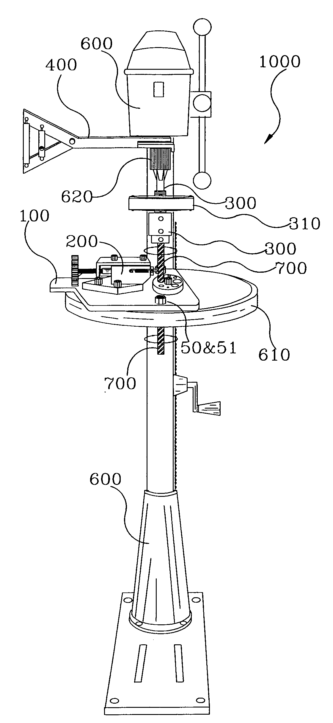
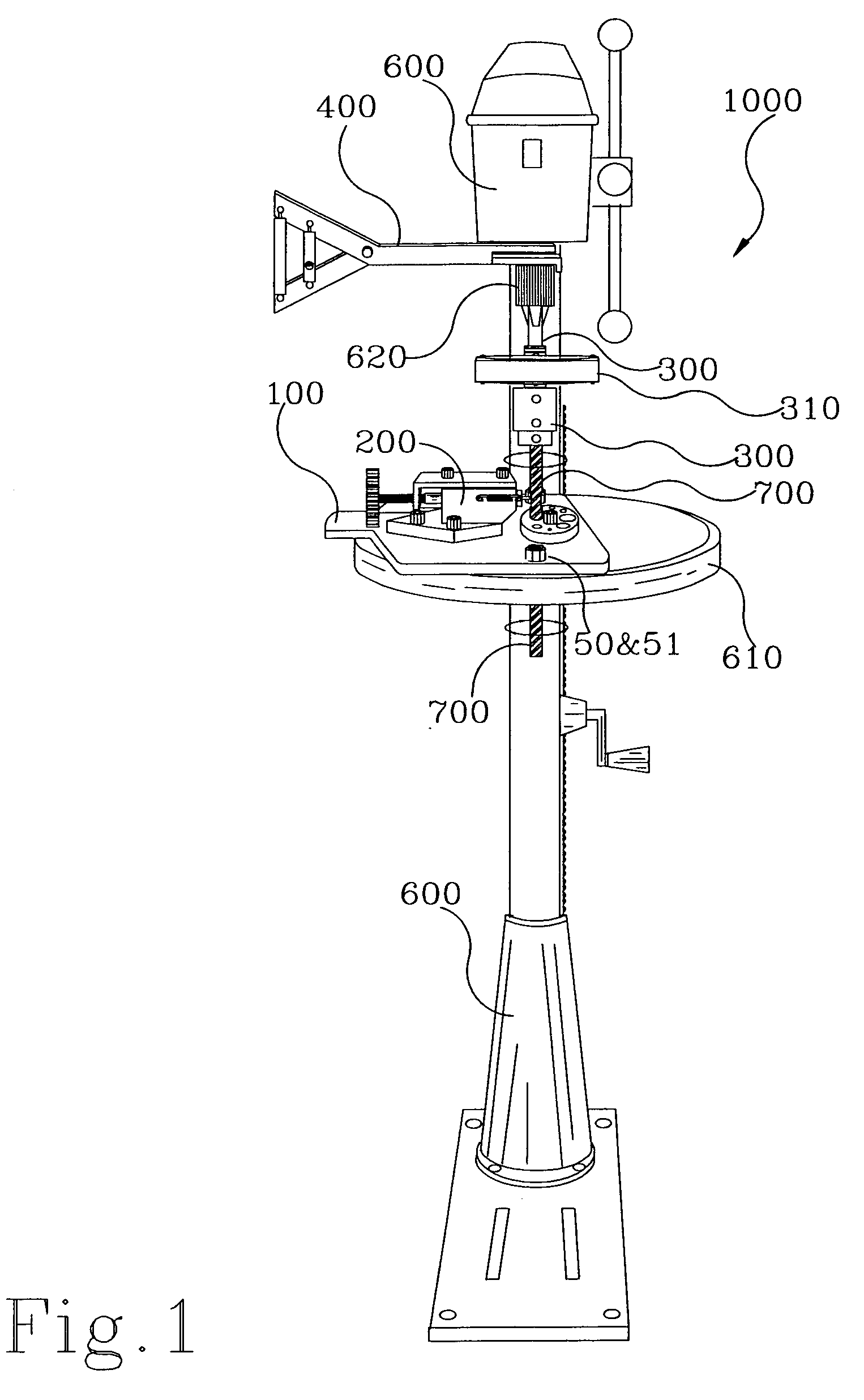
[0043]The present invention is a metal lathe (ML) 100&200, core drill adaptor 300 and rate of cut device (ROC) 400 being combined as 1000 is shown in FIG. 1 with a rate of cut device (ROC) 400 and a oil and coolant device 310 shown attached to a standard drill press 600 showing a drill press chuck 620 holding the core drill adaptor (CDA) 300 with the oil and coolant device 310 while the metal lathe (M) 100&200 is shown in motion turning work material 700. The metal lathe (ML) 100&200 is shown mounted onto the drill press work base 610 with (2) two ⅝″ mounting bolts 51 and nuts 50.

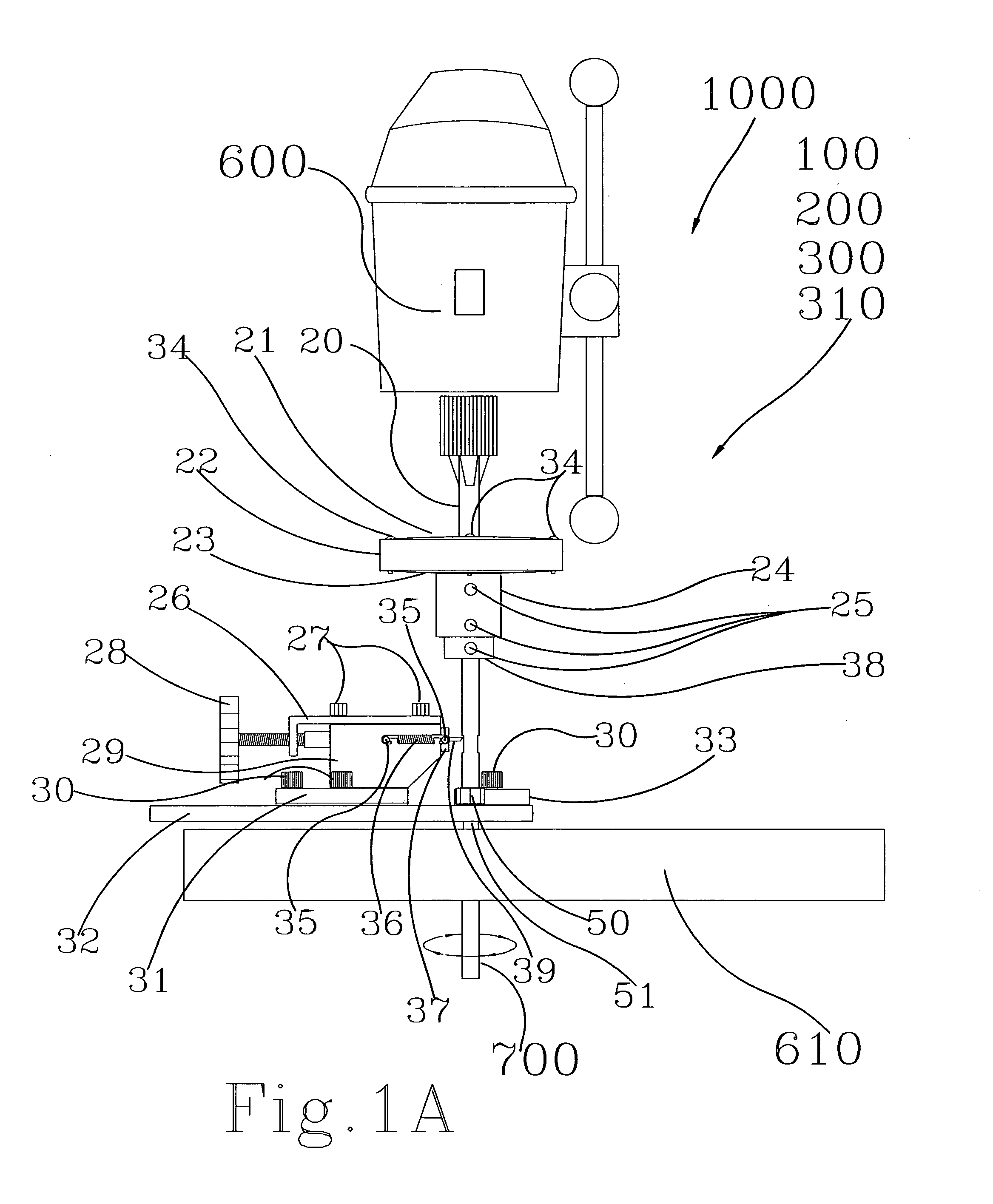
[0044]FIG. 1A is showing component parts of the metal lathe and core drill adaptor 1000, and it's component parts being as follows, main shaft of the core drill 20 transfers the power of the drill press to the core (CDA) 300 which serves as a material holder also, top cover of the oil and coolant tank 21 is sealed to the main body of tank and provides access to refill the tank with fluid thru a hole in the ...


PUM

PropertyMeasurementUnit
pressureaaaaaaaaaa
speedaaaaaaaaaa
angleaaaaaaaaaa

Abstract

The Metal Lathe, Core Drill Adaptor and Rate of Cut Device are simple lathing and drilling devices including a device that restricts the advancement of the drilling and lathing motions. These devices are attached to a most any common standard upright drilling machine in a secure method to allow a person with little or no experience to operate these devices.

Description

BACKGROUND OF THE INVENTION[0001]1. Field of the Invention[0002]The present invention relates to metal working and or machining of any materials requiring a change of diameter in any solid, round or hollow round materials by lathing, turning and or the drilling of holes in all shapes and sizes of materials regardless of configuration of that material, using a standard drill press as the power source and device used for the rotation of the materials or the cutting device.[0003]2. Description of Related Art[0004]Changing the shape of materials such as metal, wood, plastics or any other type of material has been the final goal in all aspects of trades and inventions for centuries. Lathing or reshaping of round materials by cutting away the unwanted portion of the shape. This is done by rotating or turning the material at a slow rate of speed then placing a stationary blade or cutting device onto the material with pressure. thereby removing that part of the material not wanted.[0005]Als...

Claims


Application Information

Patent Timeline
Patent Type & Authority Applications(United States)
IPC IPC(8): B23B5/00
CPCB23B3/00B23B33/00Y10T82/2527B23B51/0473B23B2250/12B23B47/00
Inventor REEVES, KENNETH LEE
Owner REEVES KENNETH LEE
Why Eureka
Try Eureka