Rearview assembly with display

a rearview mirror and display technology, applied in the field of interior rearview mirror assemblies, can solve the problems of impaired illumination, achieve the effects of reducing display image washout, dispersing heat, and enhancing illumination transmission

Inactive Publication Date: 2009-08-13
MAGNA ELECTRONICS INC
View PDF106 Cites 215 Cited by
  • Summary
  • Abstract
  • Description
  • Claims
  • Application Information

AI Technical Summary

Benefits of technology

[0013]Therefore, an aspect of the present invention provides an interior electro-optic (such as an electrochromic) rearview mirror assembly with a backlit display element and may include a visible light transflecting / polarizing element or film disposed at a rear surface or fourth surface of the electro-optical element. The visible light transflecting / polarizing element or film functions to allow substantial transmissivity of at least partially polarized light from the display element to pass through the electro-optical element for viewing by a person (such as a driver of the vehicle) viewing the mirror assembly, while providing a desired degree of reflectance of light incident on the reflective element so that the driver can use the electro-optic mirror to see rearward when driving on a highway. The display information (such as a video display of the area immediately to the rear of the vehicle as captured by a video camera mounted, such as at a rear license plate holder, at the rear of the vehicle so as to display to the driver when he / she may be reversing the vehicle any obstacles or persons immediately to the rear of the vehicle) thus may be readily viewable through and at the reflective element when the display element is activated or energized, but the display element and display area is substantially not readily viewable or not discernible by a person viewing the reflective element when the display element is deactivated or de-energized so as to be substantially covert. The display element may comprise a TFT LCD video display element and may at least partially linearly polarizes light passing therethrough, whereby the visible light transflecting / polarizing element or film is applied or disposed between the display element and the rear surface of the electro-optical element so that the polarization axes of the display element and of the visible light transflecting / polarizing element or film are generally or, preferably, substantially aligned. The reflective element and display of the present invention thus provides enhanced transmission of the illumination by the display element to reduce display image washout, while providing the desired degree of reflectivity of light incident on the reflective element. Optionally, and desirably, the mirror assembly may include a thermal conducting element in contact with the display element or display module and configured to draw heat from the display element or module and to dissipate the heat at an exterior area of the mirror assembly.

Problems solved by technology

However, successful commercialization of covert video displays that are disposed behind and whose presence behind the mirror reflector is principally visible / discernible to the driver or other occupant of the vehicle only when the display image is actuated has hitherto been impaired by display image washout during higher ambient lighting conditions, such as daylight lighting conditions, particularly on a sunny day.

Method used


Image

  • Rearview assembly with display
  • Rearview assembly with display
  • Rearview assembly with display

Examples


Embodiment Construction

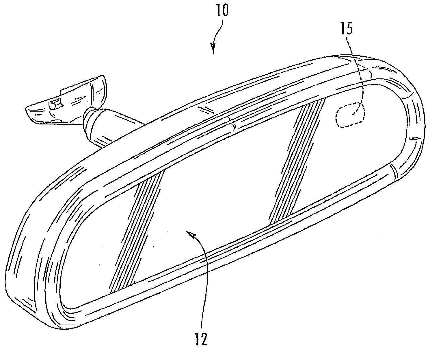
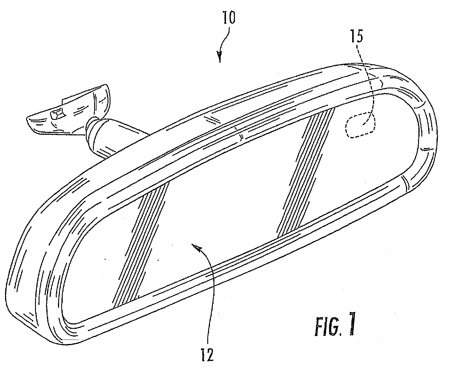
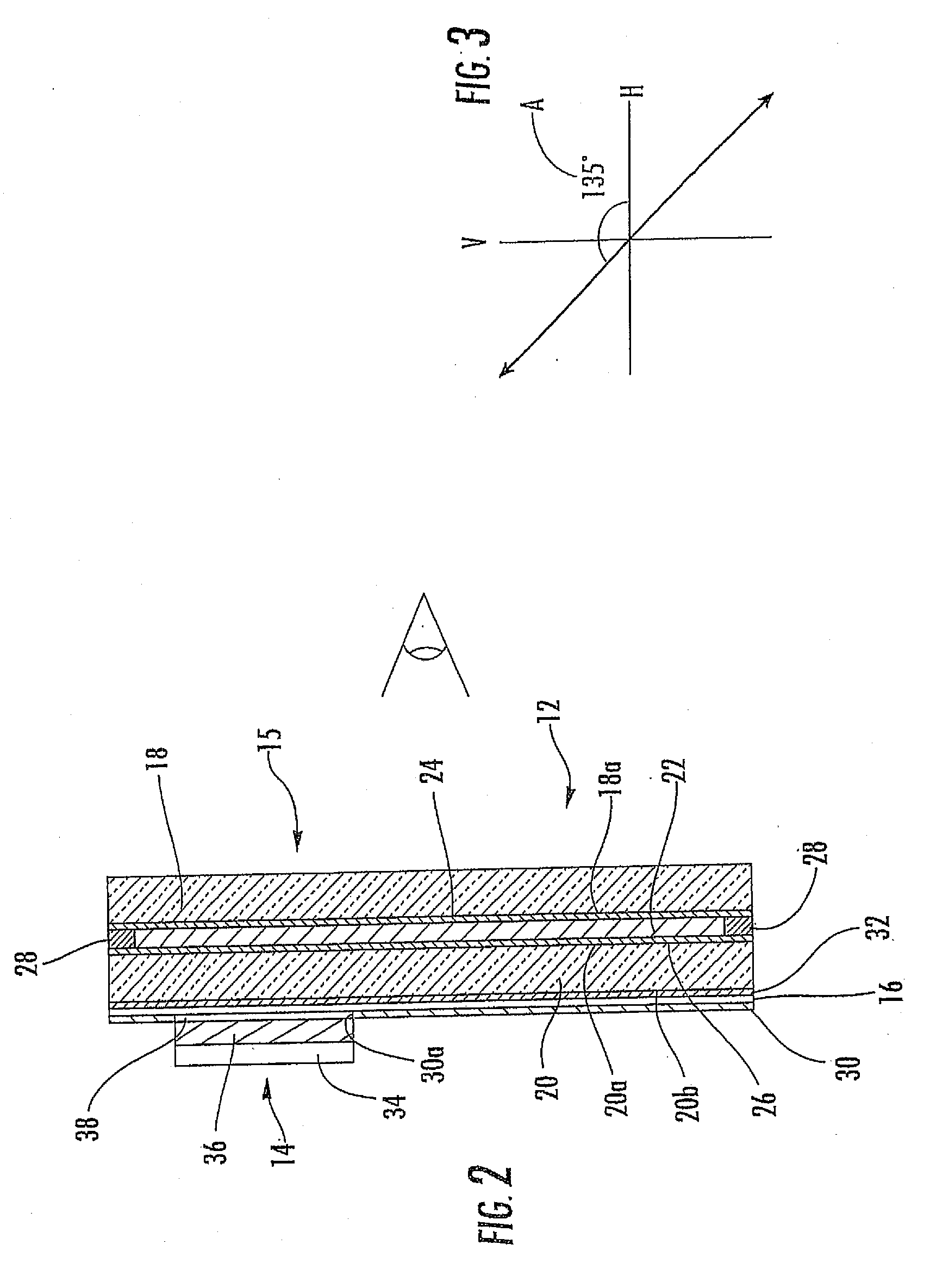
[0076]Referring now to the drawings and the illustrative embodiments depicted therein, an interior rearview mirror assembly 10 for a vehicle includes an electro-optic element assembly or cell 12 and a display device 14 at a rear surface of the electro-optic element 12 for displaying information at a display area 15 of the reflective element (FIGS. 1 and 2). Display device 14 is disposed at the rear surface of the electro-optic element 12, with a visible light transflecting / polarizing element or film or layer 16 disposed between the display device and the rear surface of the electro-optic element 12. Visible light transflecting / polarizing element or film 16 functions to substantially transmit polarized illumination emitted from the display device 14 that then passes through electro-optic element 12 while reflecting other substantially non-polarized illumination or light (typically sunlight by day or moonlight / vehicle headlamp lighting / street lighting and the like by night) that is in...


PUM

PropertyMeasurementUnit
reflectanceaaaaaaaaaa
refractive indexaaaaaaaaaa
reflectanceaaaaaaaaaa

Abstract

A rearview assembly for a vehicle includes a mirror element having a partially reflective, partially transmissive coating and a video display positioned behind the mirror element such that a display image is viewable through the partially reflective, partially transmissive coating. The video display may generate a viewable display image that has an intensity of at least 250 cd / m2. The video display may generate a display image that extends along and abuts at least a portion of curved edges of a housing. The assembly may include a forward facing light sensor for sensing a first light level forward of the vehicle, a rearward facing light sensor sensing a second light level to the rear of the vehicle, and a control circuit for comparing the first and second light levels and generating a warning signal when the second light level exceeds the first light level by at least threshold amount.

Description

CROSS REFERENCE TO RELATED APPLICATIONS[0001]The present application is a continuation of U.S. patent application Ser. No. 12 / 091,525, filed Apr. 25, 2008 (Attorney Docket DON01 P-1300), which is a 371 national phase application of PCT Application No. PCT / US2006 / 042718, filed Oct. 31, 2006, which claims the benefit of U.S. provisional applications, Ser. No. 60 / 732,245, filed Nov. 1, 2005; Ser. No. 60 / 759,992, filed Jan. 18, 2006; and Ser. No. 60 / 836,219, filed Aug. 8, 2006, which are hereby incorporated herein by reference in their entireties; and the present application is a continuation-in-part of U.S. patent application Ser. No. 11 / 935,800, filed Nov. 6, 2007 (Attorney Docket DON01 P-1401), which is a continuation of U.S. patent application Ser. No. 11 / 624,381, filed Jan. 18, 2007, now U.S. Pat. No. 7,490,007, which is a continuation of U.S. patent application Ser. No. 10 / 645,762, filed Aug. 20, 2003, now U.S. Pat. No. 7,167,796, which claims priority of U.S. provisional applicat...

Claims


Application Information

Patent Timeline
Patent Type & Authority Applications(United States)
IPC IPC(8): B60Q1/00G02F1/13B60R1/12G02F1/1335G08B5/00
CPCB60R1/12B60R2001/1215B60R2001/1223B60R2001/1253G02F2203/09G02F1/133385G02F1/157G02F2201/44G02F1/133308B60R1/02B60R1/10
Inventor WELLER, ANDREW D.LARSON, MARK L.MCCABE, IAN A.LYNAM, NIALL R.BLANK, RODNEY K.MCCAW, JOSEPH P.UKEN, JOHN T.
Owner MAGNA ELECTRONICS INC
Why Eureka
Try Eureka