

Wet Reflective Pavement Marking and Method
Active Publication Date: 2009-08-13
CROWN USA INC
View PDF28 Cites 18 Cited by
- Summary
- Abstract
- Description
- Claims
- Application Information
AI Technical Summary
Benefits of technology
[0011]The present invention provides improved road striping for highways over which vehicles pass, including raised reflective pellets that tend to provide better reflection over a longer period of time.
[0012]One form of the invention is a process of making reflective pellets for reflective marking of highways, with the process including forming a mixture of molten thermoplastic and reflective beads, the extrusion of the mixture to form an extrudate, dividing the extrudate into lengths to form the plastic extrudate into pellets, each of which contain a plurality of the plastic beads. The pellets may be cooled in liquid until the pellets become solid. The surface of the cured thermoplastic material that forms the body of the pellet may be removed so as to provide more exposure of the beads at the surface of the pellets. This provides the surface beads with enough exposure to reflect light.
Problems solved by technology
The water tends to block the light from engaging and being reflected from the beads, making the road conditions hazardous.
Regular flat striping is hard to see when wet for several reasons.
One of the problems of the prior art elevated reflective striping is that the materials of the striping wear away over time due to environmental conditions and particularly due to engagement by the wheels of vehicles on the striping.
The reflective beads tend to become loose and eventually separated from the striping, thereby diminishing the amount of reflection provided by the striping.
Even when the reflective beads are partially embedded in the striping, the beads tend to become loose and separate from the striping.
Other markings that have a renewable reflective structure tend to have a period of poor reflectivity between the time when the reflective surface has been damaged or lost and other beads have not yet been properly exposed.
And the processes for making the reflective markings as described above are expensive.
Method used
View moreImage
Smart ImageViewing Examples

Examples
example 1
[0037]
Highway glass spheres AASHTO M247 specification:44%1.9 refractive index 100 / 150 sieve glass spheres20%Titanium Dioxide Pigment 1%Yellow 83 Pigment0.5% Butvar B98 Polyvinylbutyral polymer34.5%
example 2
[0038]
Highway glass spheres AASHTO M247 specification:30%1.9 refractive index 100 / 150 sieve glass spheres35%Titanium Dioxide Pigment 8%Butvar B76 Polyvinylbutyral polymer26.8% S-2076 Plasticizer0.2%
example 3
[0039]
Highway glass spheres AASHTO M247 specification:20%1.9 refractive index 100 / 150 sieve glass spheres40%Titanium Dioxide Pigment8%Butvar B98 Polyvinylbutyral polymer22%Santotac Recycled PVB10%
Login to View More PUM
| Property | Measurement | Unit |
|---|---|---|
| Temperature | aaaaa | aaaaa |
| Temperature | aaaaa | aaaaa |
| Length | aaaaa | aaaaa |
Abstract
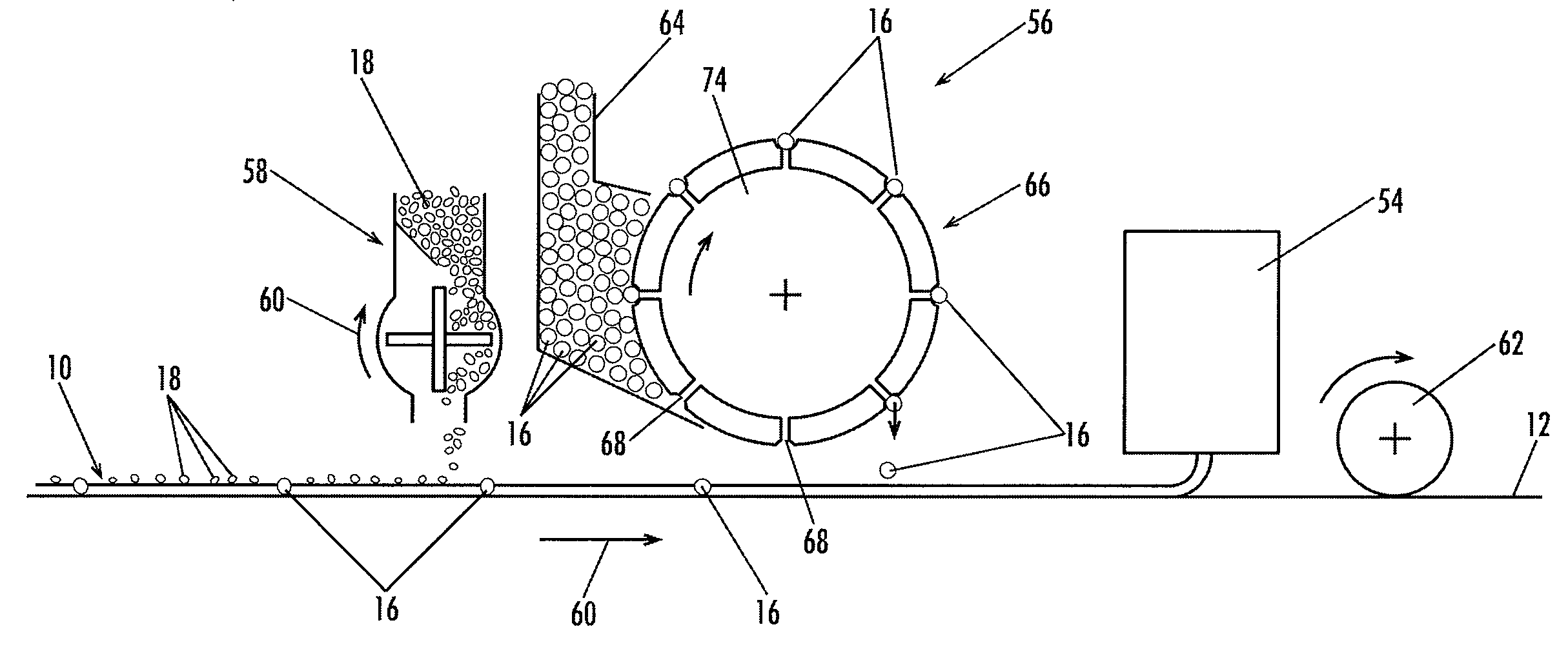
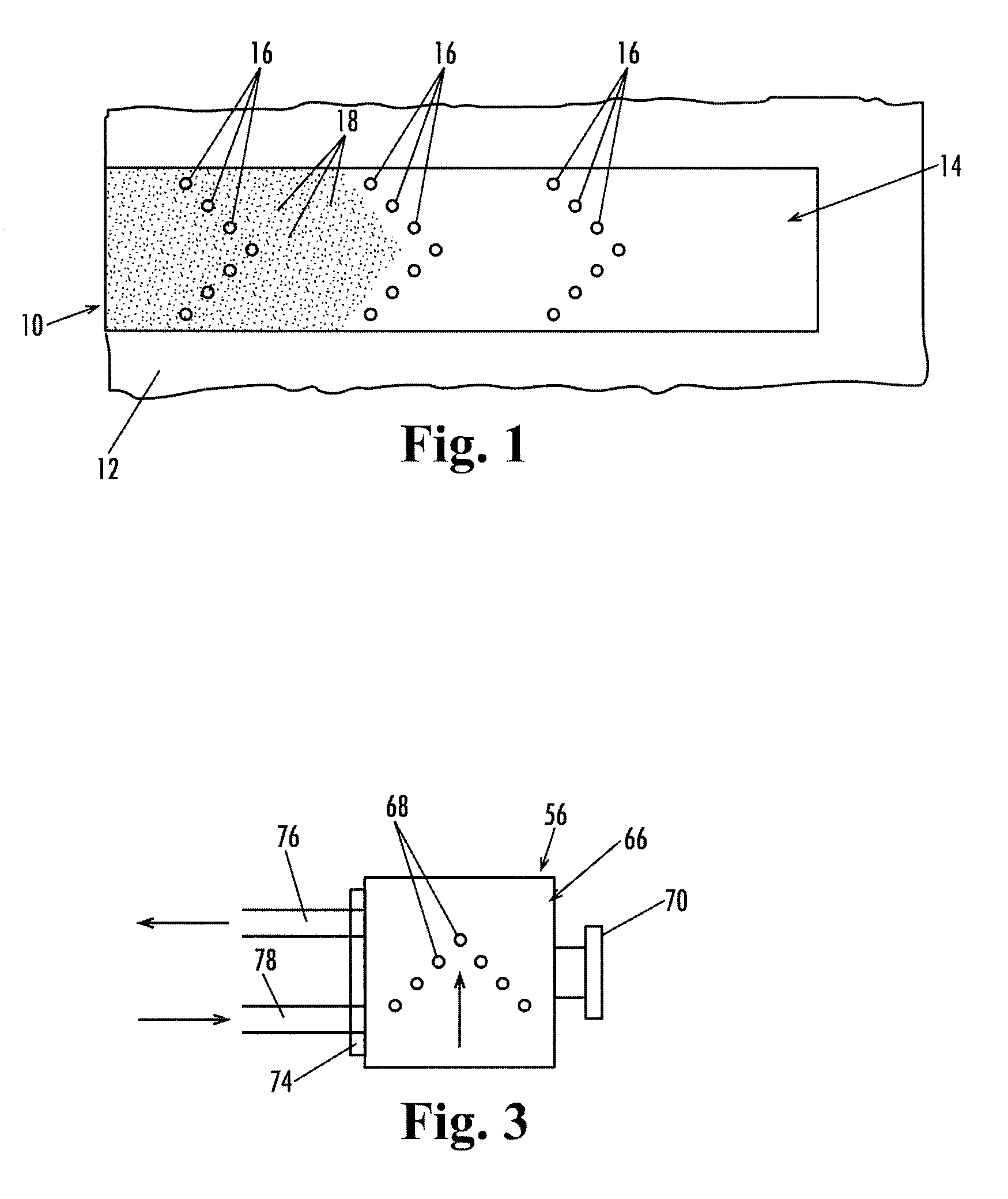
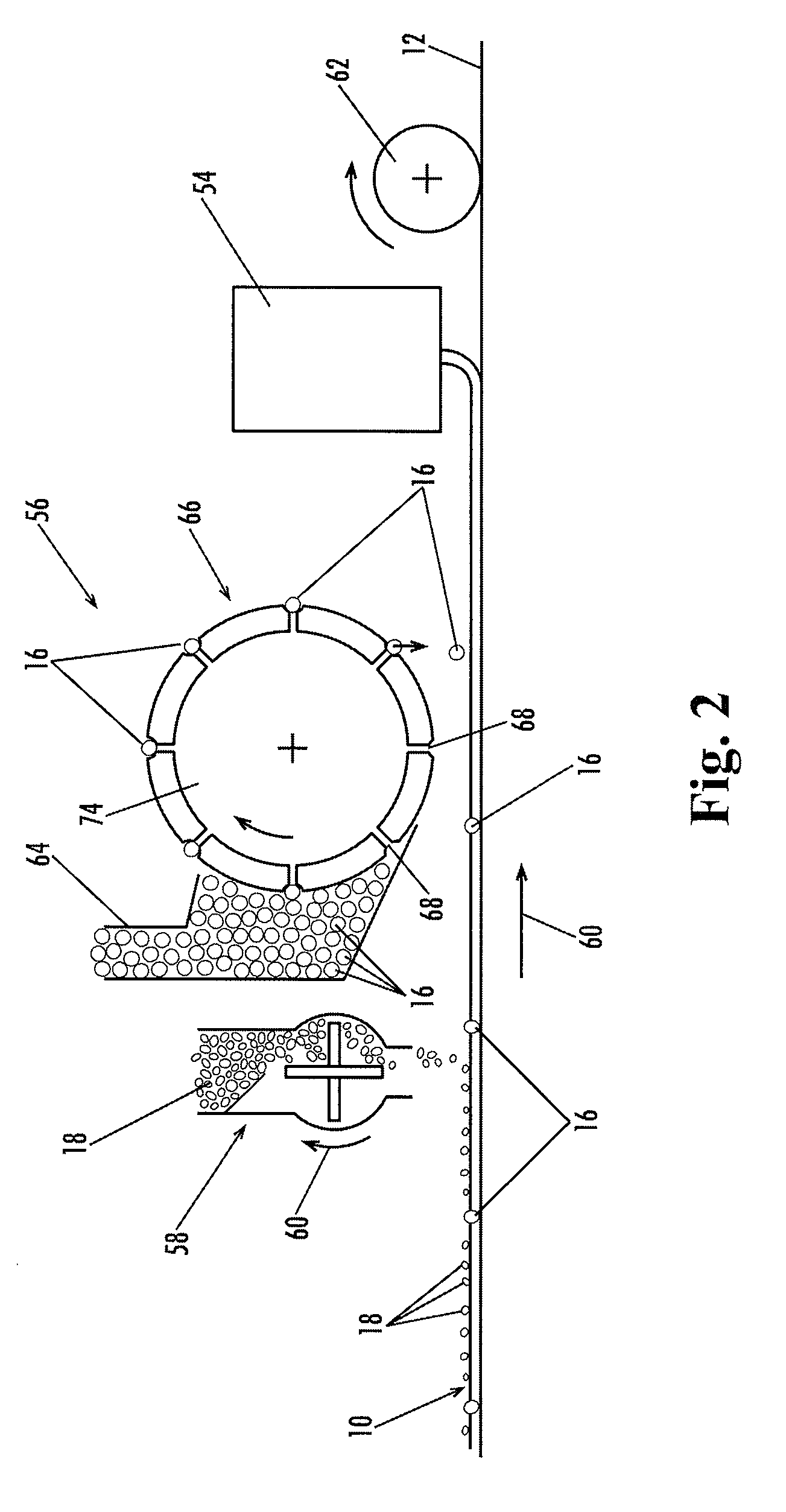
Reflective pellets (16) are formed by extrusion of reflective micro beads (26) in a thermoplastic (20), removal of the surface layer of the pellets so as to expose the reflective beads at the surface of the pellets and applying the reflective pellets to the base line (14) of the striping applied to a paved road.
Description
TECHNICAL FIELD[0001]This disclosure concerns a reflective pavement marking that includes raised pellets in a base line that are effective in reflecting light in both dry and wet conditions and the reflectivity is renewable as the surfaces wear away.BACKGROUND[0002]It is common in traffic control to use pavement markings for directing vehicles. Typically, solid lines or skip lines are formed on the surface of pavement to guide the drivers of vehicles in safe traffic flow arrangements.[0003]In order to make the pavement striping more visible in darkness, reflective beads have been added to the striping. In wet night time conditions the reflectivity of the road striping is substantially reduced because of the presence of water on the road striping. The water tends to block the light from engaging and being reflected from the beads, making the road conditions hazardous. This hazardous condition may be aggravated because the drivers may be used to having adequate reflection of the headl...
Claims
Login to View More Application Information
Patent Timeline
 IPC IPC(8): E01C23/20
CPCE01C23/166Y10S40/903
InventorBJORKLUND, MARK S.
OwnerCROWN USA INC