Eureka AIR delivers breakthrough ideas for toughest innovation challenges, trusted by R&D personnel around the world.

Apparatus and Method for PM Purification

Inactive Publication Date: 2009-08-20
TOYOTA JIDOSHA KK
View PDF5 Cites 7 Cited by
  • Summary
  • Abstract
  • Description
  • Claims
  • Application Information

AI Technical Summary

Benefits of technology

[0010]According to the PM purification apparatus of the present invention, an electric field is created by applying voltage between the center electrode and the outer peripheral electrode, whereby PM in an exhaust gas is electrically charged and the electrically charged PM is moved to the outer periphery side of the exhaust gas flow path, and as a result, a relatively large amount of PM can be trapped in the outer periphery-side region of a honeycomb support disposed in the exhaust gas flow path. In the PM purification apparatus of the present invention, the PM oxidation catalyst loading per unit volume of support in the outer periphery-side region of the honeycomb support is larger than the PM oxidation catalyst loading per unit volume of support in the inner-side region of the honeycomb support, and therefore the PM oxidation in the outer periphery-side region of the honeycomb support, where the amount of PM trapped is relatively large, is higher than the PM oxidation ability in the inner-side region of the honeycomb support, where the amount of PM trapped is relatively small.
[0011]That is, according to the PM purification apparatus of the present invention, the PM oxidation catalyst loaded on the honeycomb support can be efficiently used.
[0013]In the center of an exhaust pipe, the flow velocity of exhaust gas is greater than the outer periphery side of the exhaust tube, and the amount of NOx to be treated increases. Therefore, according to the embodiment above, the NOx purification catalyst loaded on the honeycomb support can be efficiently used.
[0014]Also, in the PM purification apparatus of the present invention, since the PM oxidation catalyst loading per unit volume of support in the outer periphery-side region of the honeycomb support is greater than the PM oxidation catalyst loading per unit volume of support in the inner-side region of the honeycomb support, according to the embodiment above, PM oxidation performance can be enhanced by increasing the ratio of the PM oxidation catalyst in the outer periphery-side region where PM is trapped in a large amount, and at the same time, NOx purification performance can be enhanced by increasing the ratio of the NOx purification catalyst in the inner-side region where a large amount of NOx to be treated flows in, which achieves both PM oxidative removal and NOx purification.
[0016]According to this embodiment, the outer periphery-side region of the honeycomb support, where PM is accumulated in a large amount, is made of an electrically conducting material, particularly a metal, so that when electrically charged PM is trapped, the electrical charge of PM can be swiftly removed. This prevents any accumulated PM from electrostatically repelling each other and coming off. Also, the inner-side region of the honeycomb support is made of an insulating material, so that electrical insulation between the outer peripheral electrode and the center electrode can be maintained.
[0021]That is, according to the method of the present invention, the PM oxidation catalyst loaded in the honeycomb support can be effectively used.

Problems solved by technology

However, when PM is trapped in such a filter, oxidative removal of PM cannot be expected to be achieved by only the heat of the exhaust, resulting in the filter being clogged with trapped PM as operation time passes, giving rise to an increase in air-flow resistance, which places a load on the engine.
In addition, in Kokai No. 2005-12098, there is in a problem that the flow rate of an exhaust gas passing through the center part of the filter is larger than the flow rate of an exhaust gas passing through the outer periphery side thereof and accordingly, the filter is readily clogged due to accumulation of PM in the center part of the filter.

Method used


Image

  • Apparatus and Method for PM Purification
  • Apparatus and Method for PM Purification
  • Apparatus and Method for PM Purification

Examples


examples

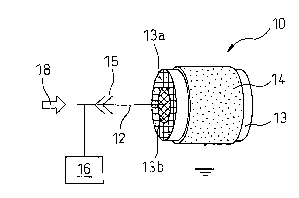
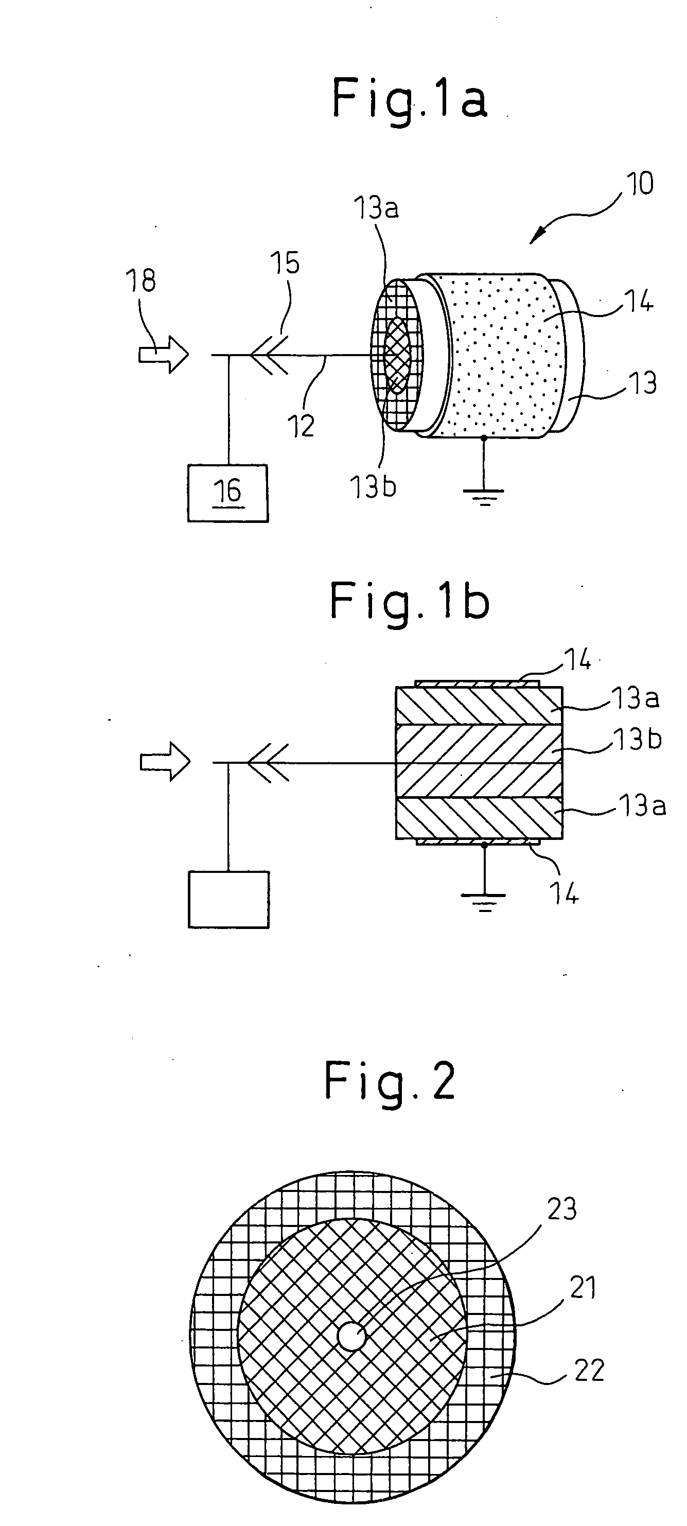
[0054]Examples and Comparative Examples were performed using a PM purification apparatus having a construction shown in FIGS. 1a and 1b. However, a needle-like electrode was not used here.

example 1

Honeycomb Support:

[0055]The honeycomb support used in Example 1 is a straight flow-type honeycomb support having a columnar shape like the honeycomb support 13 shown in FIGS. 1a and 1b. The honeycomb support of Example 1 has a cross-sectional shape shown in FIG. 2 and is formed by combining a columnar honeycomb support 21 for inner-side region and a cylindrical honeycomb support 22 of the outer periphery-side region. Here, the columnar honeycomb support 21 of the inner-side region was 82.5 mm (diameter)×155 mm (length) and had, on the center axis, a 20 mm-diameter through-hole 23 for passing a center electrode. The cylindrical honeycomb support 22 of the outer periphery-side region was 103 mm (outer diameter)×155 mm (length) and was shaped into a cylindrical form for housing the columnar honeycomb support 21 of the inner-side region. These honeycomb supports of the inner-side region and outer periphery-side region both were made of cordierite and had a cell density of 900 cpsi (cell...

example 2

[0059]The PM purification apparatus of Example 2 was produced in the same manner as the PM purification apparatus of Example 1, except that the honeycomb support of the outer periphery-side region was made of a metal. Accordingly, similarly to the PM purification apparatus of Example 1, the honeycomb support of the inner-side region was made of cordierite and both honeycomb supports had a cell density of 900 cpsi.


PUM

PropertyMeasurementUnit
Electrical resistanceaaaaaaaaaa
Densityaaaaaaaaaa
Volumeaaaaaaaaaa

Abstract

The present invention provides an apparatus and a method for PM purification, where good PM purification performance can be achieved. The PM purification apparatus 10 of the present invention comprises (a) a honeycomb support 13 having an outer periphery-side region 13a and an inner-side region 13b, which carries a PM oxidation catalyst and in which the PM oxidation catalyst loading per unit volume of support in the outer periphery-side region 13a is greater than the PM oxidation catalyst loading per unit volume of support in the inner-side region 13b, (b) a center electrode 12 passing through the center part of the honeycomb support 13 and extending to the exhaust gas flow upstream side, and (c) an outer peripheral electrode 14 disposed on the outer periphery of the honeycomb support 13 and electrically insulated from the center electrode 12 by the honeycomb support 13. The PM purification method of the present invention can be performed using the PM purification apparatus 10 of the present invention.

Description

TECHNICAL FIELD[0001]The present invention relates to an apparatus and a method for the purification of particulate matter (hereinafter referred to as “PM”) in exhaust gas from internal combustion engines and the like. More specifically, the present invention relates to a PM purification apparatus and a PM purification method for purifying PM exhausted from internal combustion engines, such as a diesel engine.BACKGROUND ART[0002]Many automobiles use diesel engines, particularly, large-size vehicles. In recent years, there is a strong demand to reduce the discharge of PM, as well as nitrogen oxide, carbon monoxide, hydrocarbon, etc., from the exhaust gas of a diesel engine. Therefore, not only development of a technique for reducing PM, for example, by improving engines or optimizing combustion conditions, but also establishing a technique for efficiently removing PM from exhaust gas, has been desired.[0003]In order to remove PM from exhaust gas, a ceramic honeycomb filter, alloy fil...

Claims


Application Information

Patent Timeline
IPC IPC(8): F01N3/01
CPCB01D53/944F01N13/017B01J23/58B01J23/63B01J37/0215B01J37/0248B03C3/013B03C3/51F01N3/0275F01N3/035F01N3/0821F01N3/0842F01N3/106F01N3/2066Y02T10/24B01D2258/012Y02T10/12
Inventor KAKINOHANA, MASARUHIRATA, HIROHITOIBE, MASAYA
Owner TOYOTA JIDOSHA KK
Why Eureka
Eureka Blog
Learn More