
Compressor Fill Method And Apparatus

a compressor and filling technology, applied in the direction of liquid handling, container discharge methods, packaging goods, etc., can solve the problems of increasing the pressure of the container, requiring too much time, and the steps of filling and cooling are impractical

Active Publication Date: 2009-08-20
AIR PROD & CHEM INC
View PDF40 Cites 41 Cited by
  • Summary
  • Abstract
  • Description
  • Claims
  • Application Information

AI Technical Summary

Benefits of technology

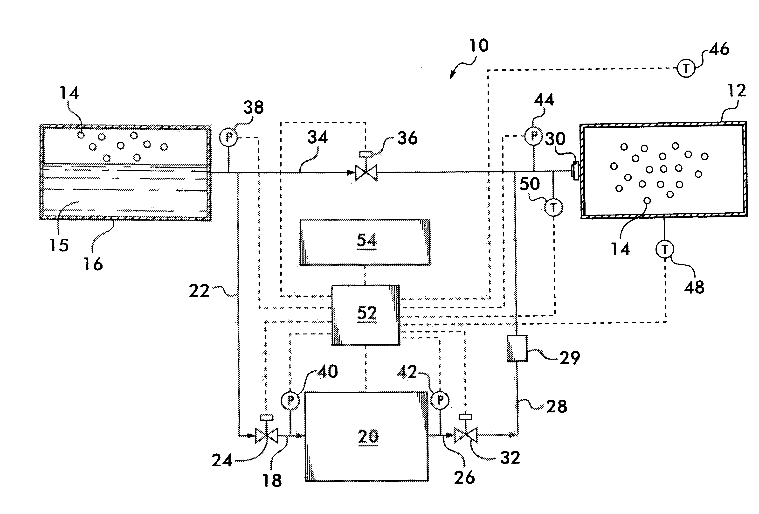
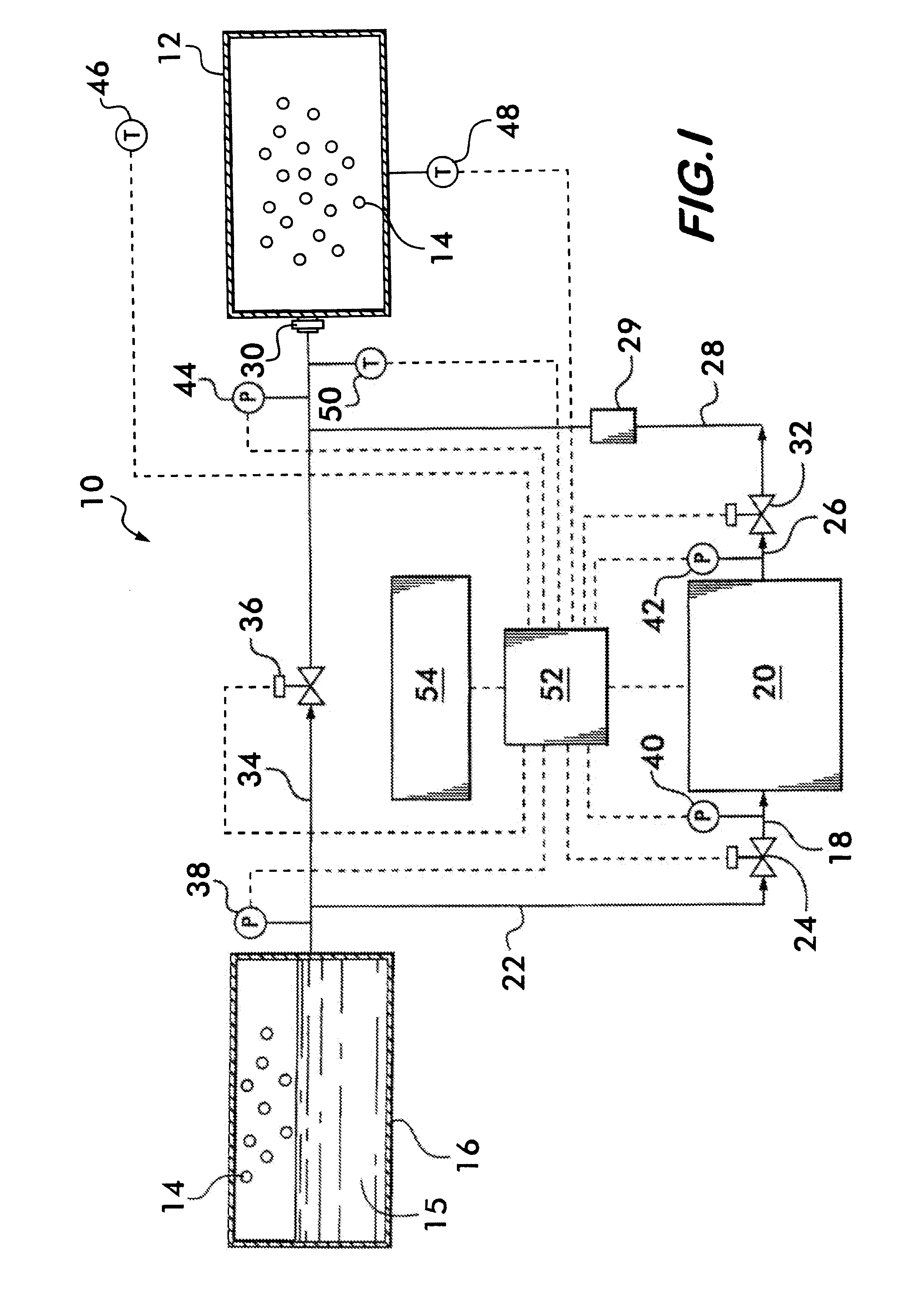
[0012]The invention also encompasses an apparatus for filling a vessel with a gas. The apparatus comprises a source of the gas and a compressing means for compressing the gas. The compressing means has a variable mass flow rate and an inlet and an outlet. A first conduit connects the source and the inlet, and a second conduit connects the outlet and the vessel. A controller controls the mass flow rate of the compressing means. A transducer measures the value of a parameter selected from the group consisting of gas pressure, gas temperature, ambient temperature and combinations thereof. The controller receives electrical signals from the transducer and uses the electrical signals to control the mass flow rate of the compressing means to fill the vessel from the source.

Problems solved by technology

The practical considerations associated with the large scale storage and dispensing of gaseous hydrogen fuel for motor vehicles presents different problems from those associated with the handling of liquid fuels due to the gaseous nature of the hydrogen.
One problem, as yet not satisfactorily addressed, is that of filling fuel tanks of various capacities, different pressures, and different ullage with gaseous hydrogen safely, over a time period comparable with the time required to fill a fuel tank of comparable energy capacity with a liquid fuel.
Additionally, any charging of a tank with compressed gas will cause the gas within the tank to heat up, increasing its pressure, the volume being fixed.
These steps of filling and cooling are impractical and require too much time compared with filling of a tank with liquid.

Method used


Image

  • Compressor Fill Method And Apparatus
  • Compressor Fill Method And Apparatus
  • Compressor Fill Method And Apparatus

Examples


Embodiment Construction

[0015]FIG. 1 shows, in schematic form, an apparatus 10 for filling a vessel 12 with a gas 14. Apparatus 10 comprises a source 16 of gas 14. The gas 14 may be stored as a liquid 15 or as the gas 14 at the source. Source 16 is connected in fluid communication with the inlet 18 of a fluid compressing means 20 by a conduit 22. The fluid compressing means 20 may comprise a variable mass flow rate pump or compressor as appropriate depending upon whether a liquid or gaseous fluid is supplied to the inlet 18. A variable mass flow rate compressor or pump may be used for liquids, whereas a variable mass flow rate compressor is used for gas fed to the inlet. The mass flow rate for these pumps and compressors is varied typically by varying the speed of the pump or compressor.

[0016]Flow of fluid (liquid 15 or gas 14) from source 16 to the compressing means inlet 18 is controlled by a valve 24 positioned within the conduit 22 between the source and the compressing means. Compressing means 20 has ...


PUM

PropertyMeasurementUnit
temperatureaaaaaaaaaa
pressure rise rateaaaaaaaaaa
temperatureaaaaaaaaaa

Abstract

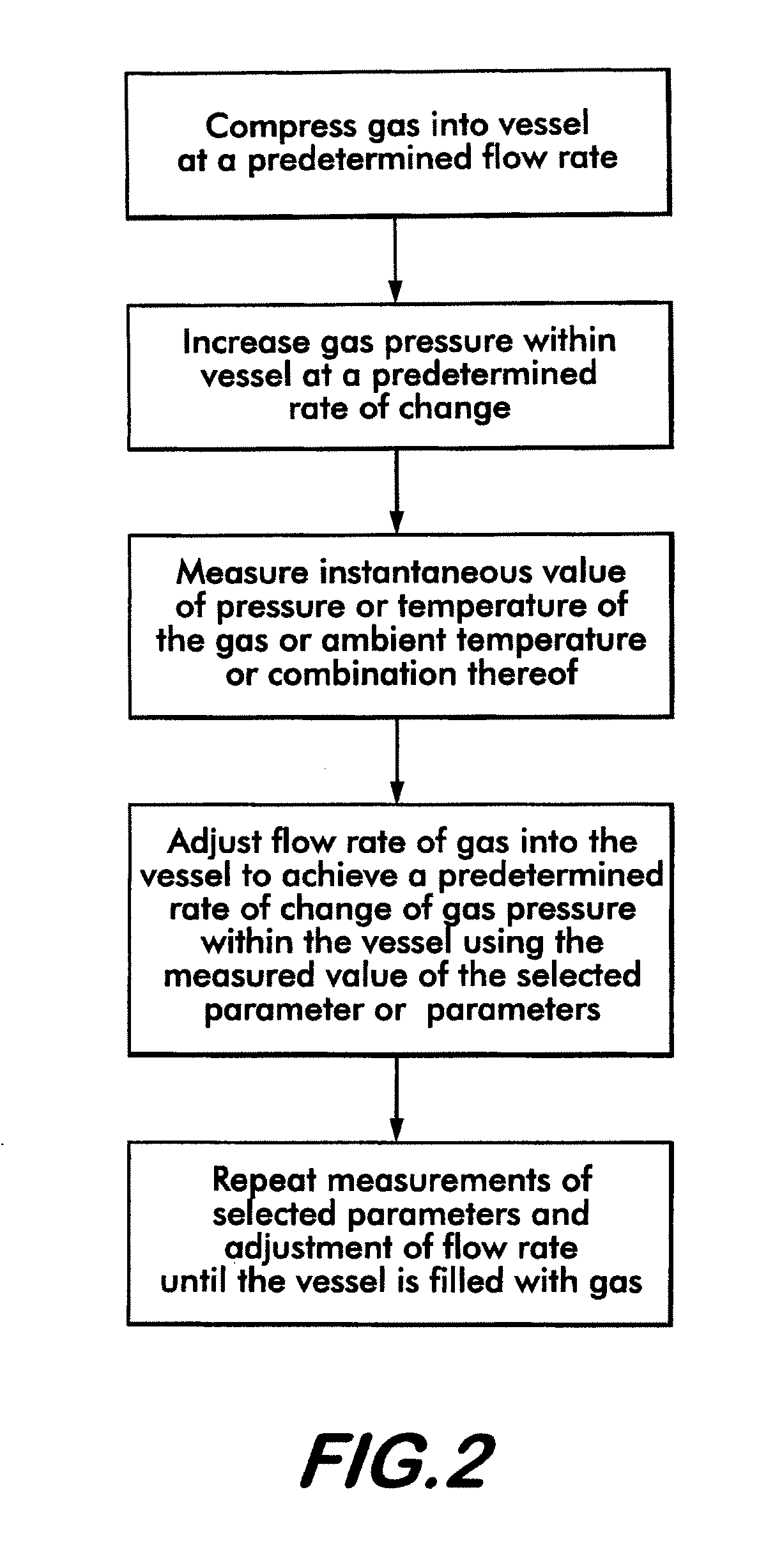
A method an apparatus for filling a vessel with compressed gas is disclosed. Gas is compressed into the vessel at a predetermined flow rate using a variable speed pump or compressor. The flow rate is adjusted to increase the gas pressure at a predetermined rate of change. The flow rate is adjusted based upon the instantaneous value of a measured parameter such as gas temperature or pressure or ambient temperature. The parameter is measured by a transducer and the value is fed back to a controller which adjusts the speed of the compressor or pump to produce the flow rate needed to achieve the predetermined pressure rate of change.

Description

BACKGROUND OF THE INVENTION[0001]This invention relates to an apparatus and a method for filling a vessel, such as a fuel tank, with a compressed gas, such as hydrogen, safely over a minimum period of time without overheating the vessel.[0002]Gaseous hydrogen is expected to supplant liquid hydrocarbon fuels, such as gasoline and diesel, as the fuel of choice for automobiles, trucks and buses due to its obvious environmental advantage. Hydrogen burns cleanly and does not produce greenhouse gases such as CO and CO2 as a combustion by-product.[0003]The practical considerations associated with the large scale storage and dispensing of gaseous hydrogen fuel for motor vehicles presents different problems from those associated with the handling of liquid fuels due to the gaseous nature of the hydrogen. One problem, as yet not satisfactorily addressed, is that of filling fuel tanks of various capacities, different pressures, and different ullage with gaseous hydrogen safely, over a time per...

Claims


Application Information

Patent Timeline
Patent Type & Authority Applications(United States)
IPC IPC(8): B65B3/10B65B3/00B65B3/26
CPCF17C2205/0326F17C13/026F17C2223/0123F17C2223/0161F17C2223/033F17C2223/035F17C2223/046F17C2225/0123F17C2225/035F17C2225/036F17C2227/0142F17C2227/0164F17C2227/0393F17C2250/032F17C2250/043F17C2250/0439F17C2250/0491F17C2250/0636F17C2260/023F17C2265/065F17C2270/0139F17C2270/0171F17C2270/0176F17C2270/0178Y02E60/321F17C5/007F17C5/02F17C5/06F17C6/00F17C7/00F17C9/00F17C13/025F17C2221/012Y02E60/32
Inventor FARESE, DAVID JOHNCOHEN, JOSEPH PERRY
Owner AIR PROD & CHEM INC
Learn More