Apparatus for treating a substrate

a technology for apparatus and substrates, applied in the direction of vacuum evaporation coatings, electrolysis components, coatings, etc., can solve the problems of worsening ignition conditions, affecting the quality of the layer, and affecting the stability of the substrate, so as to improve the stability, the effect of sheet resistance and sheet uniformity

Active Publication Date: 2009-08-20
APPLIED MATERIALS INC
View PDF9 Cites 9 Cited by
  • Summary
  • Abstract
  • Description
  • Claims
  • Application Information

AI Technical Summary

Benefits of technology

[0011]Employing this arrangement in a sputtering process, the layers of the coated substrates have a good stability over a long period of time. Furthermore, the characteristics of the layer, e.g. the sheet resistance and the sheet uniformity, are improved.

Problems solved by technology

However, the disadvantage occurs that the anodes are a hindrance for the current of plasma particles whereby the anodes are coated, too.
This coating, in turn, leads to the result that particles of the anode can fall on the substrate and worsen the quality of the layer.
As a result, the ignition conditions are worsened.

Method used


Image

  • Apparatus for treating a substrate
  • Apparatus for treating a substrate
  • Apparatus for treating a substrate

Examples


Embodiment Construction

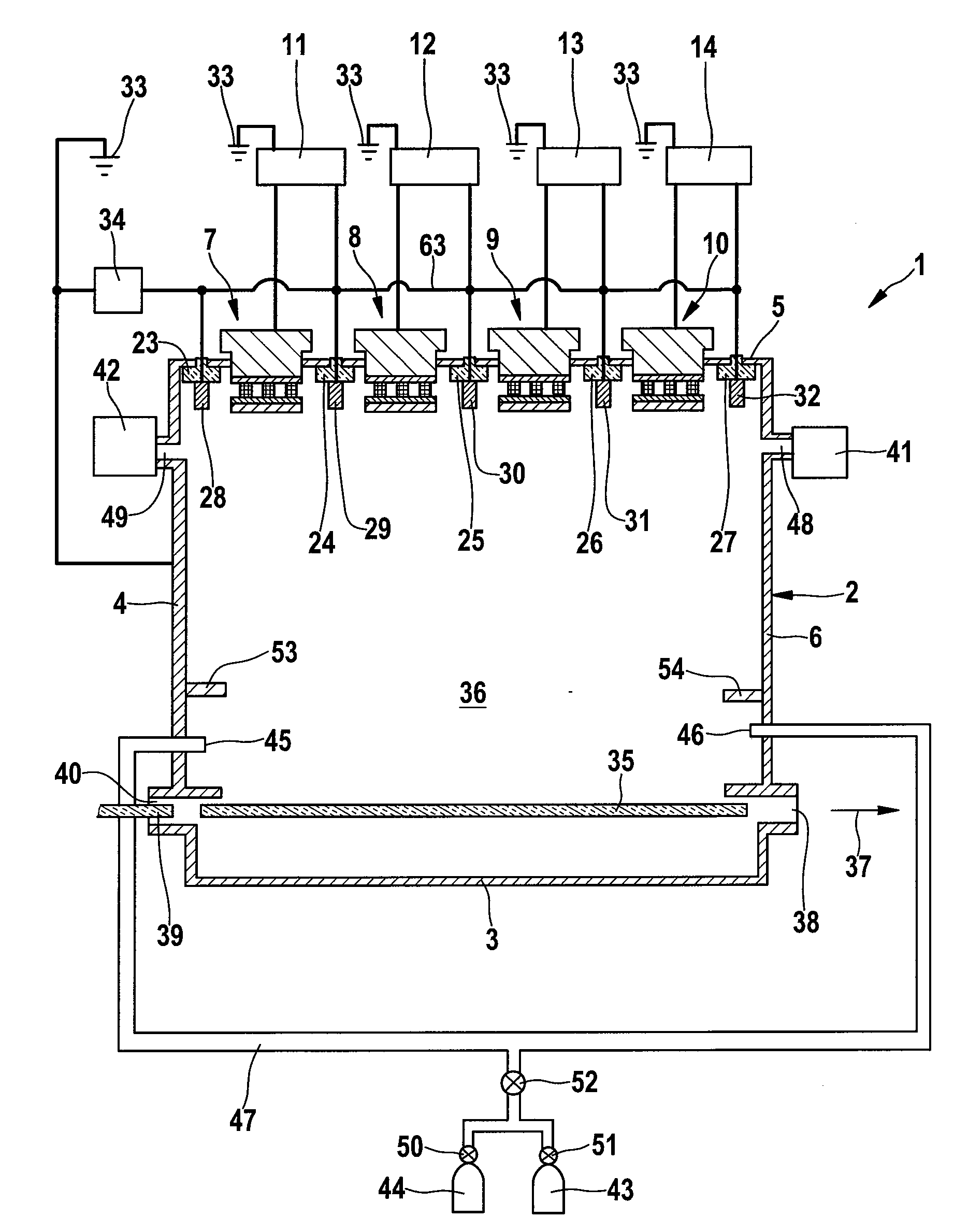
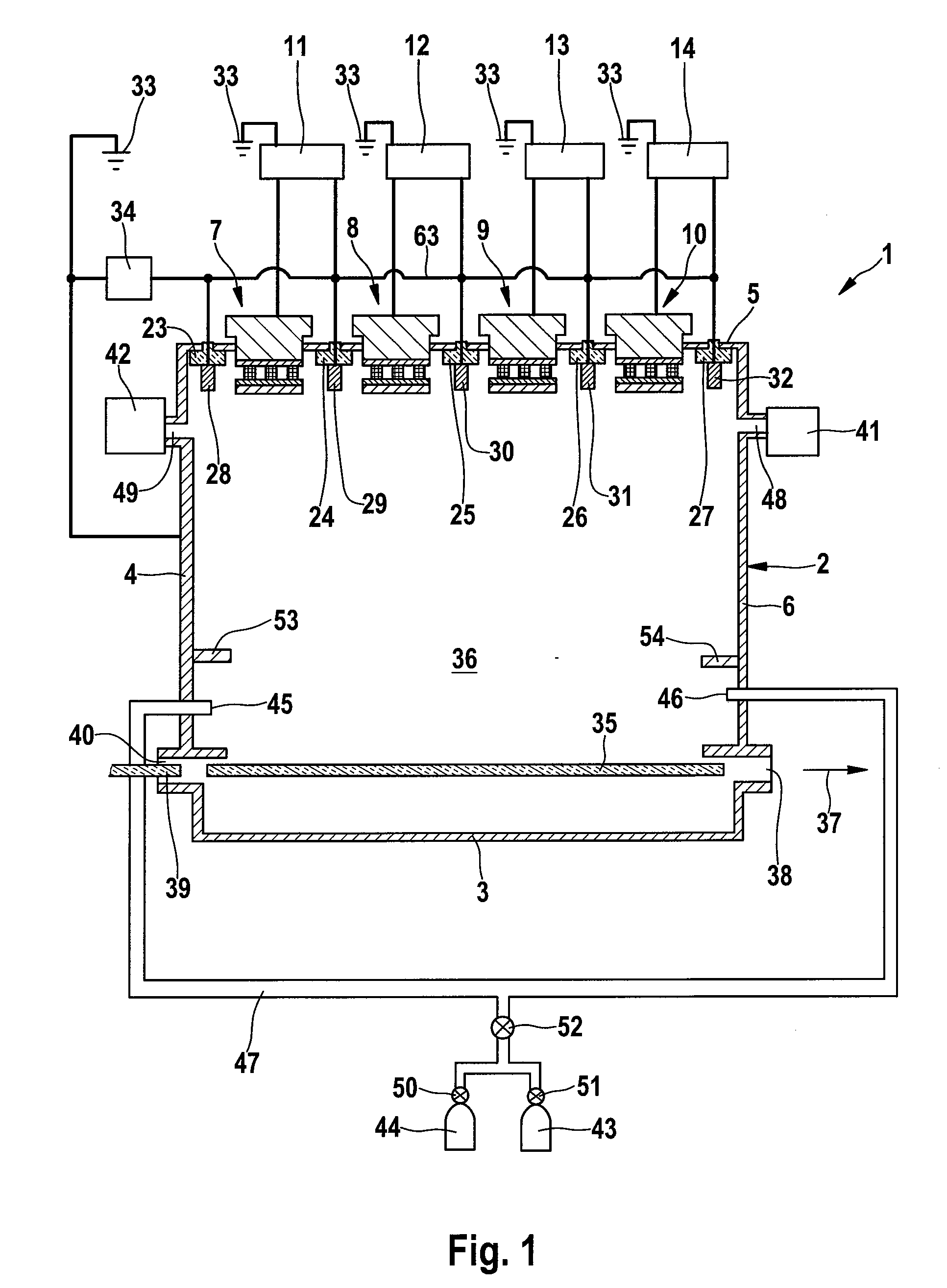
[0018]FIG. 1 shows a cross section view of an apparatus 1 for coating a substrate. This apparatus 1 comprises a vacuum chamber 2 having surrounding walls 3, 4, 5, 6 and a plurality of cathode arrangements 7 to 10. Each of the cathode arrangements 7 to 10 is connected to one of the power supplies 11 to 14 thus establishing a cathode. Anodes 28 to 32 are arranged in the neighborhood of the cathode arrangements 7 to 10 and connected via lines to the power supplies. These lines pass the wall 5 through isolators 23 to 27. The anodes 29 to 32 are connected to one of the power supplies 11 to 14 so that each power supply is connected to one of the anodes 29 to 32 and one of the cathode arrangements 7 to 10. All of these power supplies 11 to 14 are electrically connected to ground 33 serving as protective earth.

[0019]The resistance between the anodes 28 to 32 and the supplying lines is about 100-200 mΩ. If the resistance of resistor 34 is lower than 2Ω, a greater current will flow to the shr...


PUM

PropertyMeasurementUnit
resistanceaaaaaaaaaa

Abstract

This invention relates to an apparatus (1) for treating, e.g. coating, a substrate (35, 39) in a vacuum chamber (2). In this vacuum chamber (2) there are arranged n cathodes (7-10) and n+1 anodes (28-32), each of said anodes adjacent to a cathode (7-10). Each of the n cathodes (7-10) and n of the assigned anodes (29-32) are connected to a power supply (11-14). One of the anodes (28) not being assigned to a cathode (7-10) is connected to an electrical line (63) which is connecting each of the anodes (28-32). A pull-down resistor (34) is connected to said line (63) at its one end and to ground (33) at its other end.

Description

FIELD OF THE INVENTION[0001]This invention relates to an apparatus for treating a substrate.BACKGROUND OF THE INVENTION[0002]Magnetron sputtering sources are used for treating, e.g. coating, a substrate, such as semiconductors, optical devices or flat panel displays. By such magnetron sources ions of a plasma are caused to sputter material from a target. This sputtered target material is then deposited on a surface of said substrate in order to form a thin film. Also, the ions may etch the substrate.[0003]A sputter source having at least two electrically isolated stationary bar-shaped target arrangements mounted one alongside the other and separated by respective slits is already known (U.S. Pat. No. 6,093,293, see also U.S. Pat. No. 6,284,106 and U.S. Pat. No. 6,454,920). Each of the target arrangements includes a respective electric pad so that each target arrangement may be operated electrically independently from the other target arrangement. Each target arrangement also has a c...

Claims


Application Information

Patent Timeline
Patent Type & Authority Applications(United States)
IPC IPC(8): C23C14/00
CPCC23C14/352H01J37/3438H01J37/34
Inventor HANIKA, MARKUSSTOLLEY, TOBIAS
Owner APPLIED MATERIALS INC
Why Eureka
Try Eureka