Gas flow rate control valve

Inactive Publication Date: 2009-08-20
GRAND MATE
View PDF0 Cites 33 Cited by
  • Summary
  • Abstract
  • Description
  • Claims
  • Application Information

AI Technical Summary

Benefits of technology

[0007]The present invention has been accomplished under the circumstances in view. It is the main objective of the present invention to provide a gas flow rate control valve, which dir

Problems solved by technology

According to the aforesaid prior art design, the gas flow rate control is limited to the design of the gas flow rate control holes, i.e., the gas flow rate control holes allow regulation of the gas flow rate step by step, however they do not allow for linear gas flow rate control.
This inconvenient gas flow rate control method cannot satis

Method used


Image

  • Gas flow rate control valve
  • Gas flow rate control valve
  • Gas flow rate control valve

Examples


Embodiment Construction

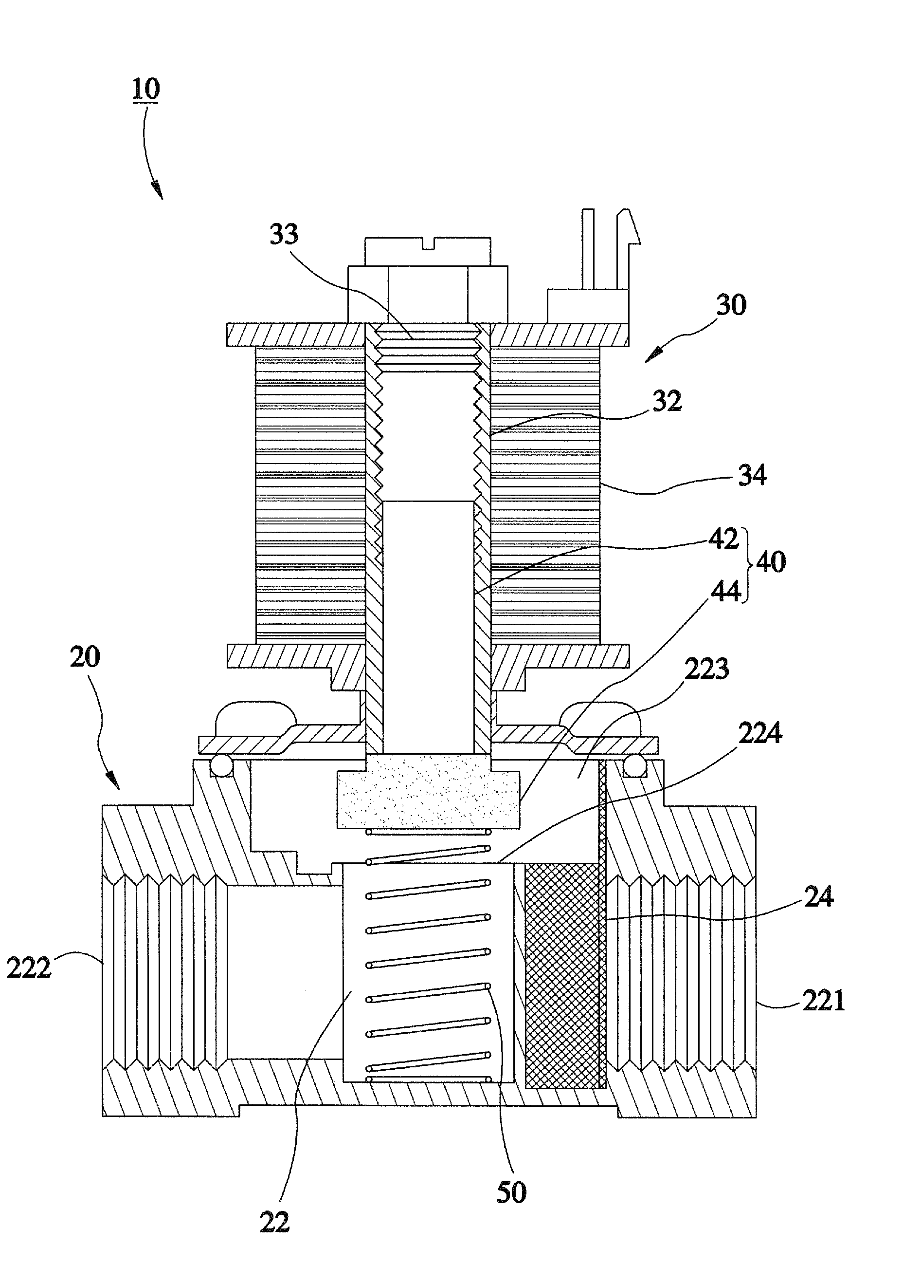
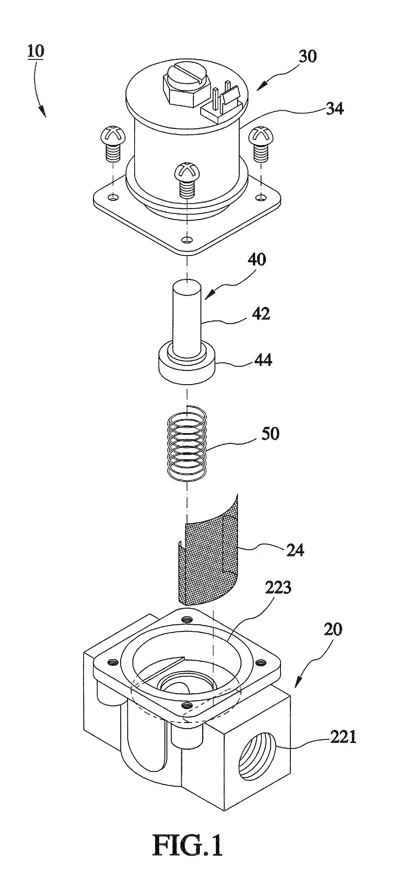
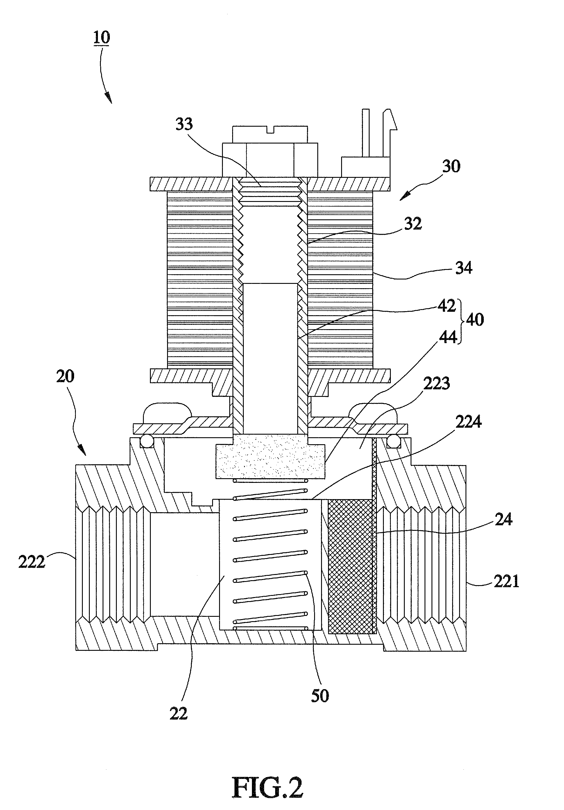
[0020]Referring to FIG. 1, a gas flow rate control valve 10 in accordance with a first embodiment of the present invention is shown comprised of a lower valve block 20, an upper valve block 30, a magnetic column 40, and a spring member 50.

[0021]The lower valve block 20 comprises a gas flow passage 22 for the passing of a fuel gas. The gas flow passage 22 comprises a gas inlet 221, a gas outlet 222, a communication hole 224 between the gas inlet 221 and the gas outlet 222, and an opening 223 located above the communication hole 224. The inlet 221 is for letting the fuel gas go into the inside of the lower valve block 20. The outlet 221 is for letting the fuel gas to out of the lower valve block 20. The opening 223 is in communication with a middle part of the passage 22 and located at the top side of the lower valve block 20. Normally, the fuel gas flows through the gas inlet 221 to the opening 223 and then flows through the communication hole 224 and then the as outlet 222 to the ou...


PUM


Abstract

A gas flow rate control valve includes a lower valve block defining a gas flow passage, and an upper valve block having a tube disposed ill communication with the gas flow passage, and a solenoid coil assembly surrounding the tube for generating a magnetic field. A magnetic column has a magnetic portion inserted into the tube and axially movable by the magnetic field generated by the solenoid coil assembly, and a stopper movable with the magnetic portion to change the open cross-sectional area of the gas flow passage so as to control the flow rate of the fuel gas passing through the gas flow passage. A spring member is provided at one of the top and bottom sides of the magnetic column to keep the magnetic column in balance and to provide a return force to the magnetic column after displacement of the magnetic column.

Description

BACKGROUND OF THE INVENTION[0001]1. Field of the Invention[0002]The present invention relates generally to gas equipments and more particularly, to a gas flow rate control valve for controlling the flow rate of a fuel gas accurately.[0003]2. Description of the Related Art[0004]Taiwan patent publication number M322516 discloses a gas flow rate control valve. According to this design, the gas flow rate control valve comprises a rotary gas supply control disk and a fixed gas supply control disk. The rotary gas supply control disk has multiple gas flow rate control holes that have different diameters. The fixed gas supply control disk has a guide hole. By means of selectively setting one gas flow rate control hole of the rotary gas supply control disk into communication with the guide hole of the fixed gas supply control disk, the fuel gas is allowed to pass through the gas flow rate control valve. By means of selectively shifting the gas flow rate control holes of the rotary gas supply...

Claims


Application Information

Patent Timeline
IPC IPC(8): F16K31/06
CPCF16K31/082F23N5/245F23N1/005
Inventor HUANG, CHIN-YINGHUANG, HSIN-MINGYEN, CHUNG-SHENG
Owner GRAND MATE
Why Eureka
Try Eureka