Unitary high pressure slip seal cartridge

a high-pressure slip seal and cartridge technology, applied in the direction of adjustable joints, mechanical devices, instruments, etc., can solve the problems of substantial expense, and achieve the effect of facilitating routine maintenan

Active Publication Date: 2009-08-20
STONEAGE
View PDF36 Cites 9 Cited by
  • Summary
  • Abstract
  • Description
  • Claims
  • Application Information

AI Technical Summary

Benefits of technology

[0005]The present invention provides a cartridge assembly comprising the wearable parts of a rotary face seal for use in a high pressure rotary waterjet tool. The cartridge is positioned within and at the inlet end of the tool and is readily accessible and removable through the opening used to provide a supply of operating fluid. The seal cartridge is pre-assembled as a “drop-in” unit to facilitate routine maintenance yet provides for sufficient relative movement between components within the cartridge and between the cartridge and tool to insure complete sealing of the liquid path.
[0006]Among the objects of the invention is to simplify the replacement of wearing parts of a small high pressure spray nozzle seal to facilitate replacement of the wearable parts.
[0007]Another object of the invention is to minimize the time required to replace wearing parts of a rotary face seal in a high pressure waterjet tool.
[0008]Another object of the invention is to insure the accuracy of assembly of wearing parts when such parts are replaced in the field.
[0010]Another object of the invention is to provide an inexpensive assembly containing all the wearing parts for small diameter rotating high pressure spray nozzle.
[0011]Another object of the invention is to provide simple access to all the wearing parts for small diameter rotating high pressure spray nozzle.

Problems solved by technology

Since these parts are subject to wear in use they require regular replacement as a part of normal maintenance.
Such high pressure rotary cleaning tools are commonly used for cleaning or descaling of industrial equipment, for example boilers, where downtime of can result in substantial expense.

Method used


Image

  • Unitary high pressure slip seal cartridge
  • Unitary high pressure slip seal cartridge
  • Unitary high pressure slip seal cartridge

Examples


Embodiment Construction

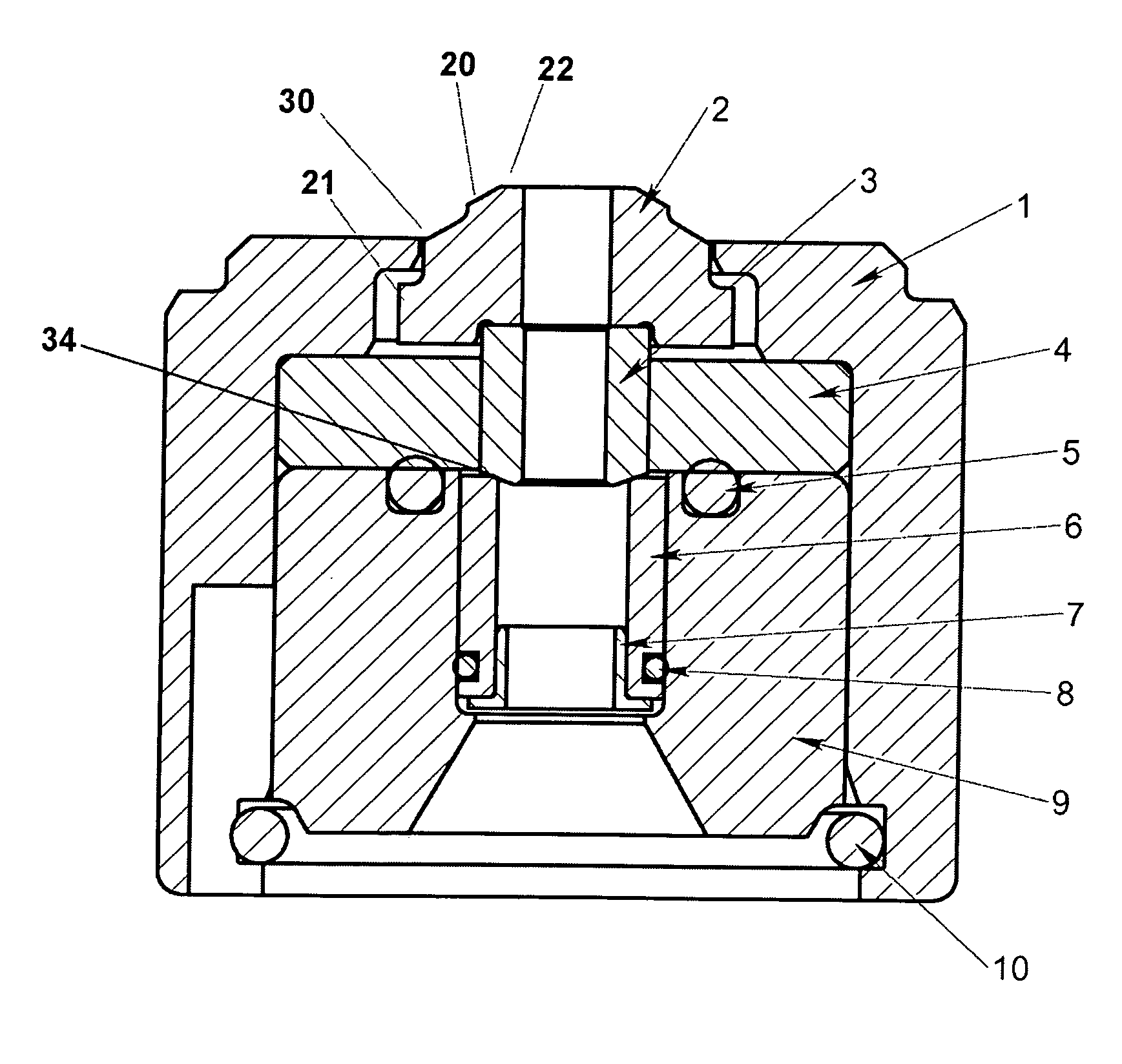
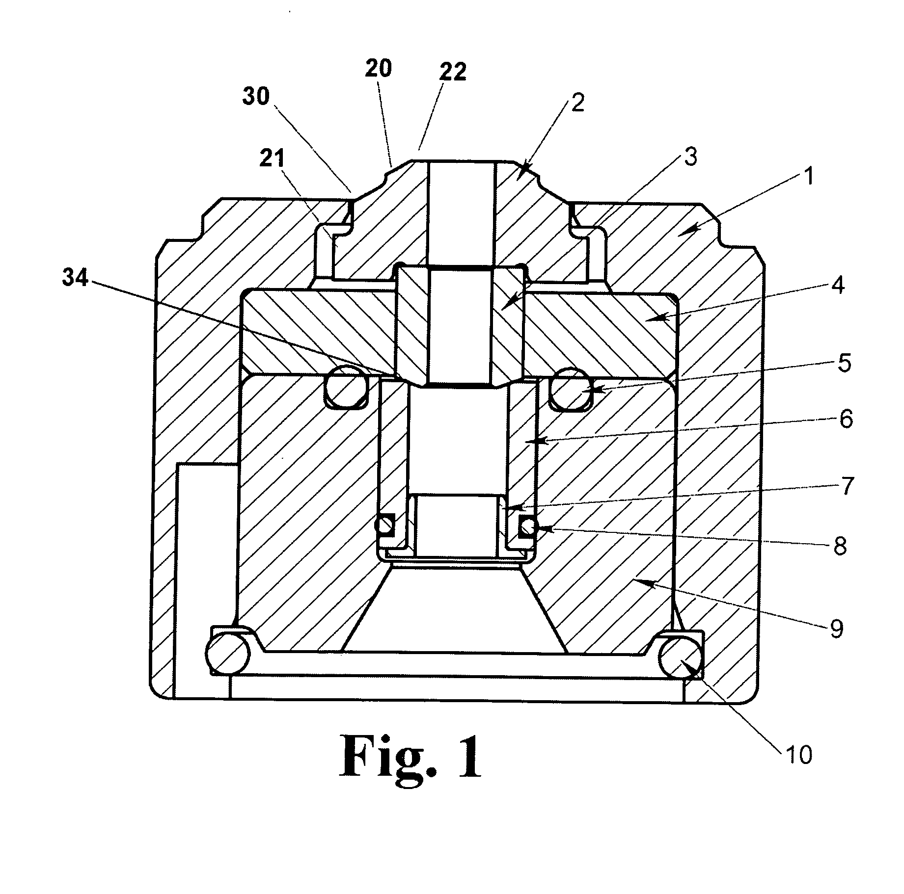
[0015]The cartridge assembly of the preferred embodiment as shown in FIG. 1 is adaptable to use in any high pressure rotary device having relatively rotatable elements such as the main body or housing B and shaft C shown in the representative tool of FIG. 3. The cartridge A is positioned within and at the inlet end of the tool and is readily accessible, insertable and removable through the axial opening E used to provide a supply of operating fluid. The seal cartridge A is held in place by a simple O-ring 11 which provides simple retention of the cartridge when the tool is non-operational or detached from a source of operating fluid such as a hose or similar fluid line. Such a hose, when attached, is threaded into inlet nut 12 thereby fully securing the cartridge in place.

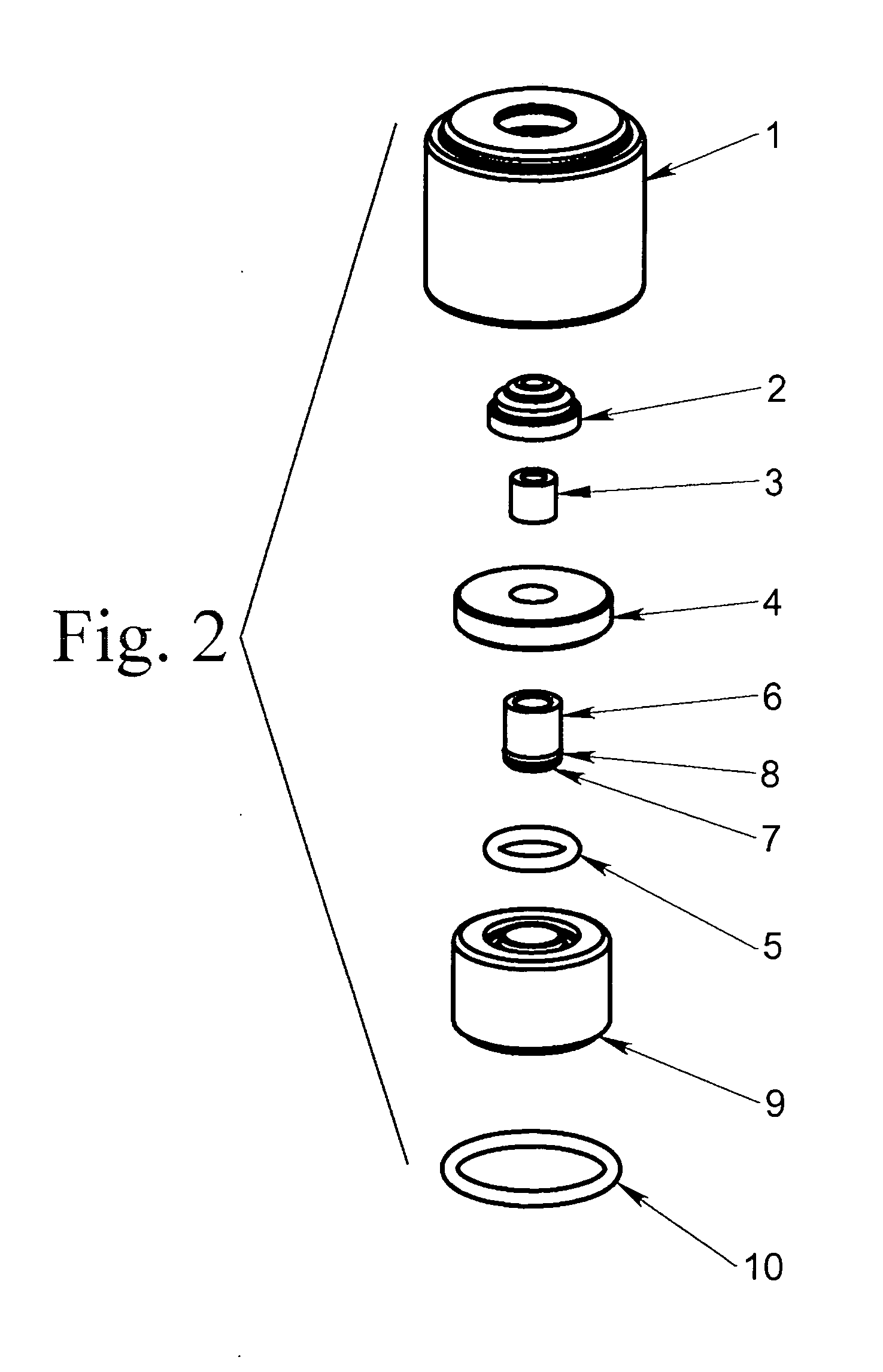
[0016]The seal assembly A is contained within a generally thimble-shaped outer housing 1 preferably machined of an appropriate grade of stainless steel or other similarly suitable material. A small diameter outer p...


PUM


Abstract

A unitary cartridge seal assembly for a high pressure liquid sealing connection between two relatively rotatable liquid passage members of a rotary nozzle or a swivel and a tool having such an assembly. The assembly comprises a thimble shaped or cylindrical housing having a flanged retainer fitting within an axial orifice to hold the components together while allowing sufficient axial movement to insure complete sealing of the respective elements. The assembly provides “drop-in” replacement of wearable parts of the rotary face seal of a high pressure water jet blasting tool.

Description

[0001]This application claims the benefit of provisional application No. 61 / 011,342 filed Jan. 15, 2008.[0002]This invention relates to simplification of the replacement of wearing parts of seals between two relatively rotatable devices having connected high pressure liquid passages.BACKGROUND OF THE INVENTION[0003]In the field of high pressure rotary liquid handling devices operating parameters can exceed 10,000 psi, rotating speeds of 1,500 rpm and flow rates of 25 gpm. Accordingly the rotary seals required to work under such constraints generally require careful and precise assembly of the relative moving parts. An example of such a seal is shown in applicant's prior U.S. Pat. No. 6,059,202 (Zink et al) which is incorporated herein by reference.[0004]Rotary face seals as used in such devices may incorporate numerous relatively small parts. While the mating portions of the rotating seals are relatively simple and inexpensive, they may require some degree of precision of assembly t...

Claims


Application Information

Patent Timeline
Patent Type & Authority Applications(United States)
IPC IPC(8): F16J15/32B41J29/00B42D15/00B42D15/10G03G21/04H04N1/387
CPCB42D25/00B42D2035/44B05B3/026B05B15/18B42D25/23B42D25/309B42D25/318B42D25/405
Inventor WRIGHT, DOUGLAS E.
Owner STONEAGE
Why Eureka
Try Eureka