Capacitor-based position sensor for vehicle

a position sensor and capacitive technology, applied in the direction of resistance/reactance/impedence, instruments, measurement devices, etc., can solve the problems of reducing affecting the ability of the sensor to function, and reducing the complexity and expense of the sensor

Inactive Publication Date: 2009-08-20
DELPHI TECH INC
View PDF8 Cites 12 Cited by
  • Summary
  • Abstract
  • Description
  • Claims
  • Application Information

AI Technical Summary

Benefits of technology

[0005]A position sensor includes an external moving element couplable to a moving part whose position is sought to be sensed. A sealed enclosure is engaged with the moving element such that the moving element moves relative to the enclosure, and first and second capacitive elements are in the enclosure and define a plane between them. An internal moving element is inside the enclosure and is magnetically coupled to the external moving element for movement therewith. The internal moving element moves in the plane to thereby change the capacitance between the capacitive elements as the external moving element moves.

Problems solved by technology

Magnetic-based contactless sensors that use, e.g., Hall sensors have been introduced and while effective, tend to require a plethora of parts such as flux concentrators that increase the complexity and expense of the sensor.
As understood herein, capacitor-based contactless sensors can be used to sense position, but suffer from the drawback of contaminant build-up between the plates (typically, one plate on the moving part and one on the non-moving part) that establish the capacitor.
This eventually ruins the ability of the sensor to function.

Method used


Image

  • Capacitor-based position sensor for vehicle
  • Capacitor-based position sensor for vehicle
  • Capacitor-based position sensor for vehicle

Examples


Embodiment Construction

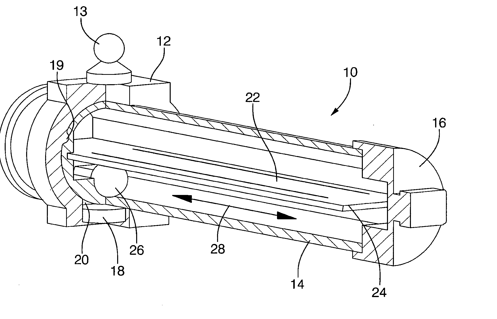
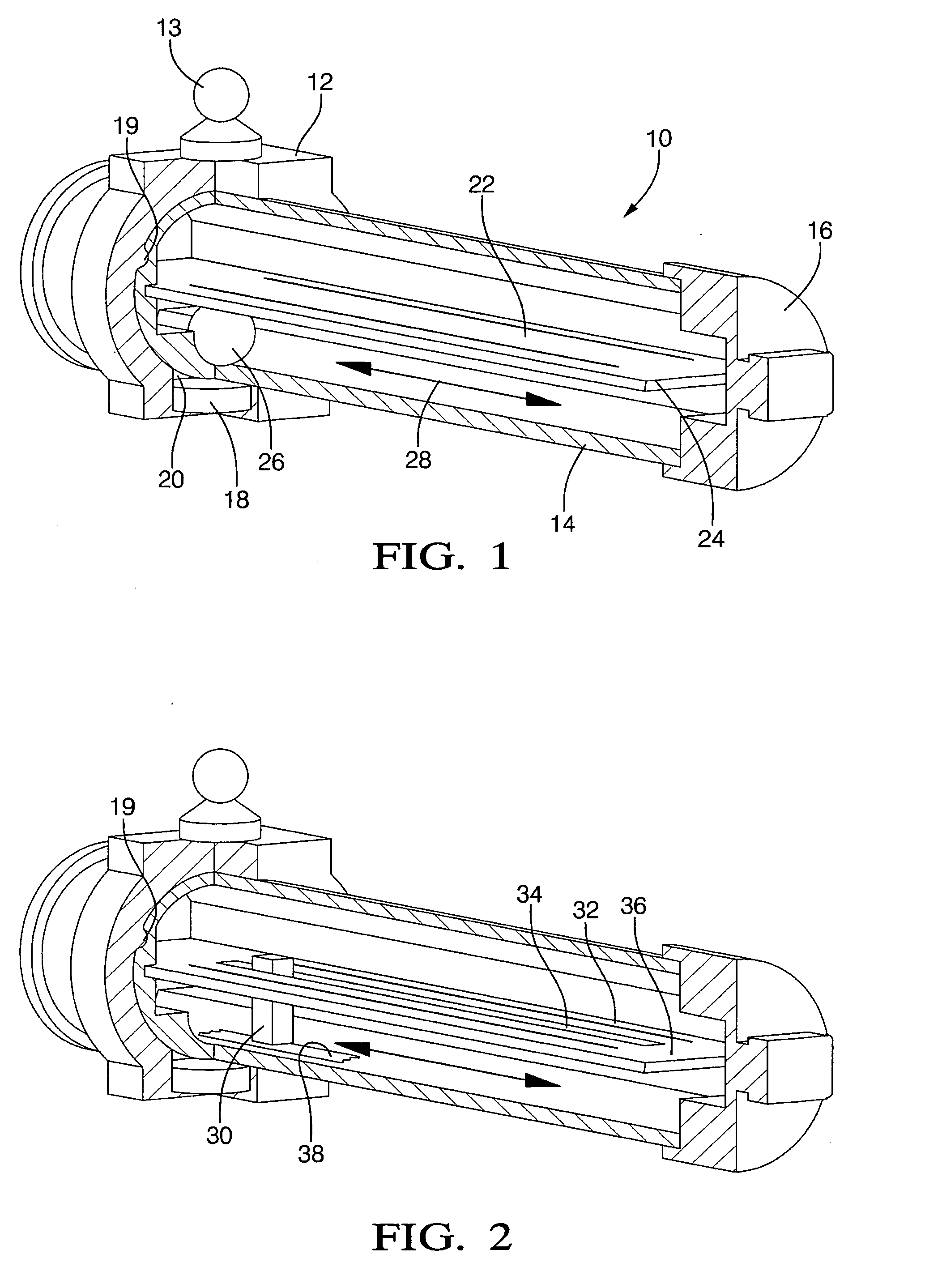
[0015]Referring initially to FIG. 1, a linear position sensor is shown, generally designated 10, that includes a sliding element 12 which is external to and which moves linearly relative to a sealed housing 14. The sliding element 12 can be coupled via a coupling post 13 to a vehicle component that moves linearly so that as the component moves, the sliding element 12 moves relative to the housing 14. In the particular embodiment shown, the housing 14 is a hollow, generally cylindrical structure the ends of which can be covered by base covers 16, while the sliding element 12 establishes a movable collar around the housing 14. One or more magnets 18 are coupled to the sliding element 12 by, e.g., press-fitting the magnet 18 into a magnet receptacle 20 of the sliding element 12. The sliding element 12 can be formed with anti-rotating structure such as but not limited to a guide protrusion 19 that moves in a groove or slot formed in the housing 14 to prevent rotational motion of the sli...


PUM


Abstract

A position sensor has an external moving element couplable to a moving part whose angular or linear position is sought to be sensed. A sealed enclosure is engaged with the moving element such that the moving element moves relative to the enclosure, and capacitive elements are in the enclosure. An internal moving element inside the enclosure is magnetically coupled to the external moving element for movement with the external element, with the internal moving element moving between the capacitive elements thereby change the capacitance between the capacitive elements as the external moving element moves.

Description

FIELD OF THE INVENTION[0001]The present invention relates generally to capacitor-based vehicle position sensors.BACKGROUND OF THE INVENTION[0002]A variety of vehicle systems require knowing the angular or linear position (and / or their derivatives of angular or linear velocity) of various components. For example, in drive-by-wire systems the position of an accelerator pedal must be known to know how much fuel to inject into the engine, since mechanical linkages between the throttle and pedal may not exist. As another example, the angular position of a crankshaft, if known, can be used in distributorless ignition systems that have selectively energized ignition coils that fire the spark plugs as appropriate for the angular position of the crankshaft. Moreover, the crankshaft angular position signals can be used for combustion control and diagnostic functions.[0003]While contact position sensors have been used, for a number of reasons contactless position sensors are preferred. Magneti...

Claims


Application Information

Patent Timeline
Patent Type & Authority Applications(United States)
IPC IPC(8): G01R27/26
CPCG01D5/2405
Inventor SANCHEZ, FRANCISCO J.URQUIDI, CARLOS A.
Owner DELPHI TECH INC
Why Eureka
Try Eureka