System and method for increasing visibility of critical flight information on aircraft displays

a technology for aircraft displays and critical flight information, applied in the field of display systems, can solve the problems of reducing the effectiveness and accuracy of flight decisions, affecting affecting the operation of aircraft displays, so as to increase the visibility of critical flight information, enhance the situational awareness of flight crews, and increase the transparency of segments

Active Publication Date: 2009-08-20
HONEYWELL INT INC
View PDF18 Cites 70 Cited by
  • Summary
  • Abstract
  • Description
  • Claims
  • Application Information

AI Technical Summary

Benefits of technology

[0009]The present invention provides an improved system and method for increasing the visibility of critical flight information on electronic displays, such as, for example, Primary Flight Displays and similar types of aircraft displays, and also electronic displays for spacecraft, unmanned air vehicles (UAVs) and associated ground stations, submarines, etc. In accordance with a preferred embodiment of the present invention, an aircraft display system is provided that includes a processing unit, a flight management system, a navigation system, a database for storing target data and terrain data, a graphics display generator, and a visual display. The flight management system and / or the navigation system provide real-time aircraft operational and flight control information. The processing unit directs the graphics display generator to generate graphic control signals for the visual display, which increase the transparency of a segment of a zero pitch reference line in the vicinity of a flight path marker on the display. Thus, critical flight information in the vicinity of the flight path marker is not obscured by the zero pitch reference line displayed in that vicinity, which enhances a flight crew's situational awareness and facilitates aircraft control. The processing unit also increases the transparency of any flight path information indicator (e.g., heading, course, track indicator) that is located near the generated segment of the zero pitch reference line, and the transparency of the zero pitch reference line where it coincides with any flight information tape or scale (e.g., airspeed tape, altitude tape, etc.) being displayed. Consequently, critical flight information near the segment of the zero pitch reference line in the vicinity of the flight path marker is not obscured by the flight path information indicator being displayed in that vicinity, and the readings on the flight information tapes are not obscured by the zero pitch reference line.

Problems solved by technology

However, a significant problem that exists with prior art Primary Flight Displays and similar types of displays is that the visual symbols representing this critical flight information are typically displayed at or near the same locations (e.g., in the center) of the display, and some of these symbols can overlap and obscure the view of others.
Consequently, a pilot's view of that pitch and heading information, and any targets or terrain features in that region, can be obscured by the flight path marker on the display, which decreases the effectiveness and accuracy of the flight decisions being made.
Notwithstanding the distinct advantages of the use of Primary Flight Displays and similar electronic displays in modern aircraft, display 100 in FIG. 1 illustrates a significant drawback of these types of displays.
Specifically, some of the flight information symbols being displayed can overlap other flight information symbols, and the overlapping symbols can obscure the pilot's view of the critical flight information that the pilot needs to see.
When approaching a runway, multiple flight symbols, such as, for example, heading select symbol, track select symbol, heading readout numbers, heading scales, etc. would typically appear in the vicinity of the flight path marker, thus causing significant visual clutter.
As such, this loss of visual contact of such critical flight information by a pilot decreases the effectiveness and accuracy of the flight decisions being made, and thus increases the possibility that flight management, navigation or control errors can occur.

Method used


Image

  • System and method for increasing visibility of critical flight information on aircraft displays
  • System and method for increasing visibility of critical flight information on aircraft displays
  • System and method for increasing visibility of critical flight information on aircraft displays

Examples


Embodiment Construction

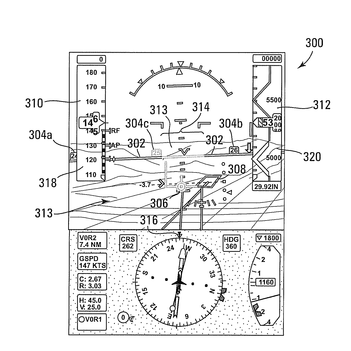
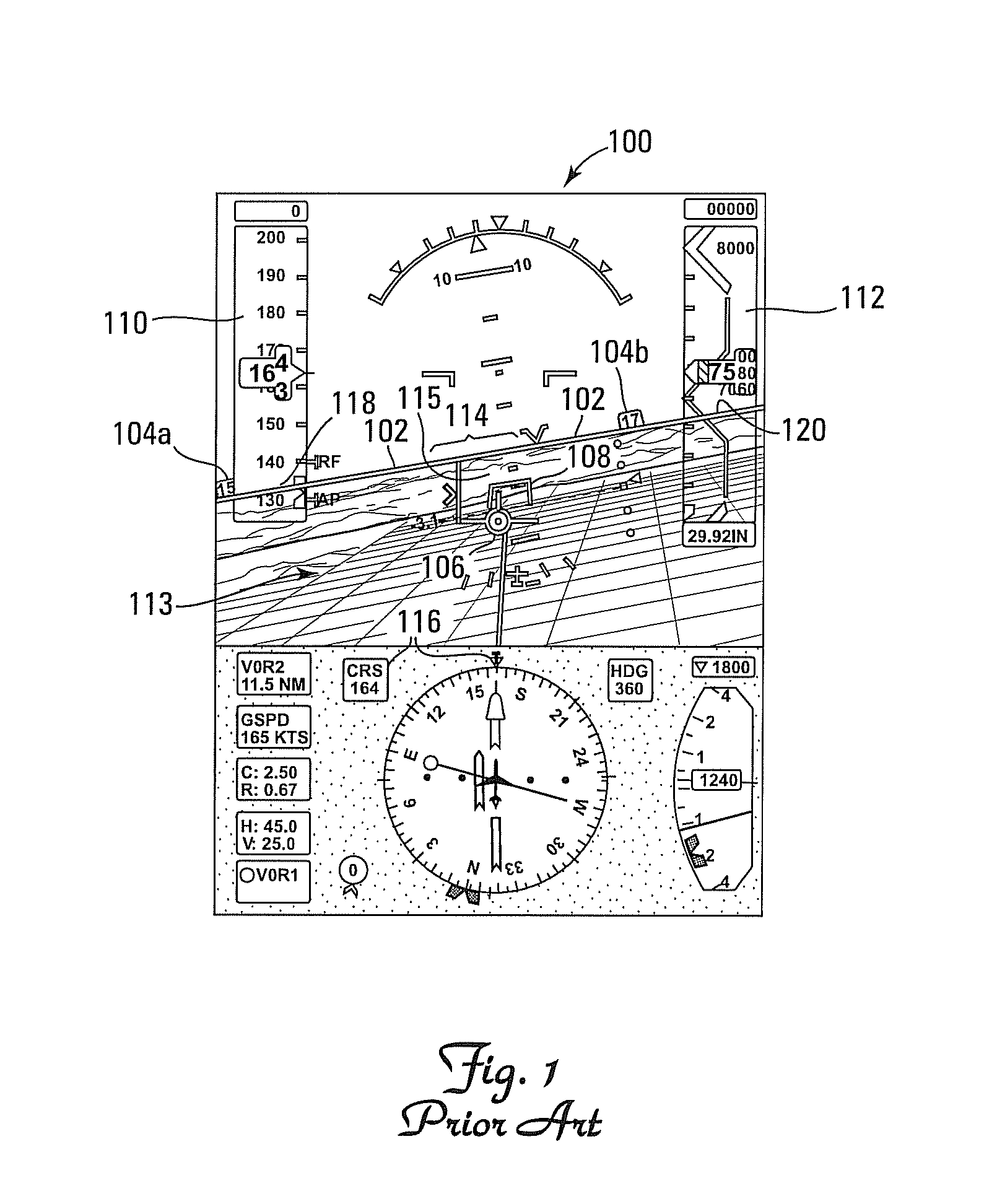
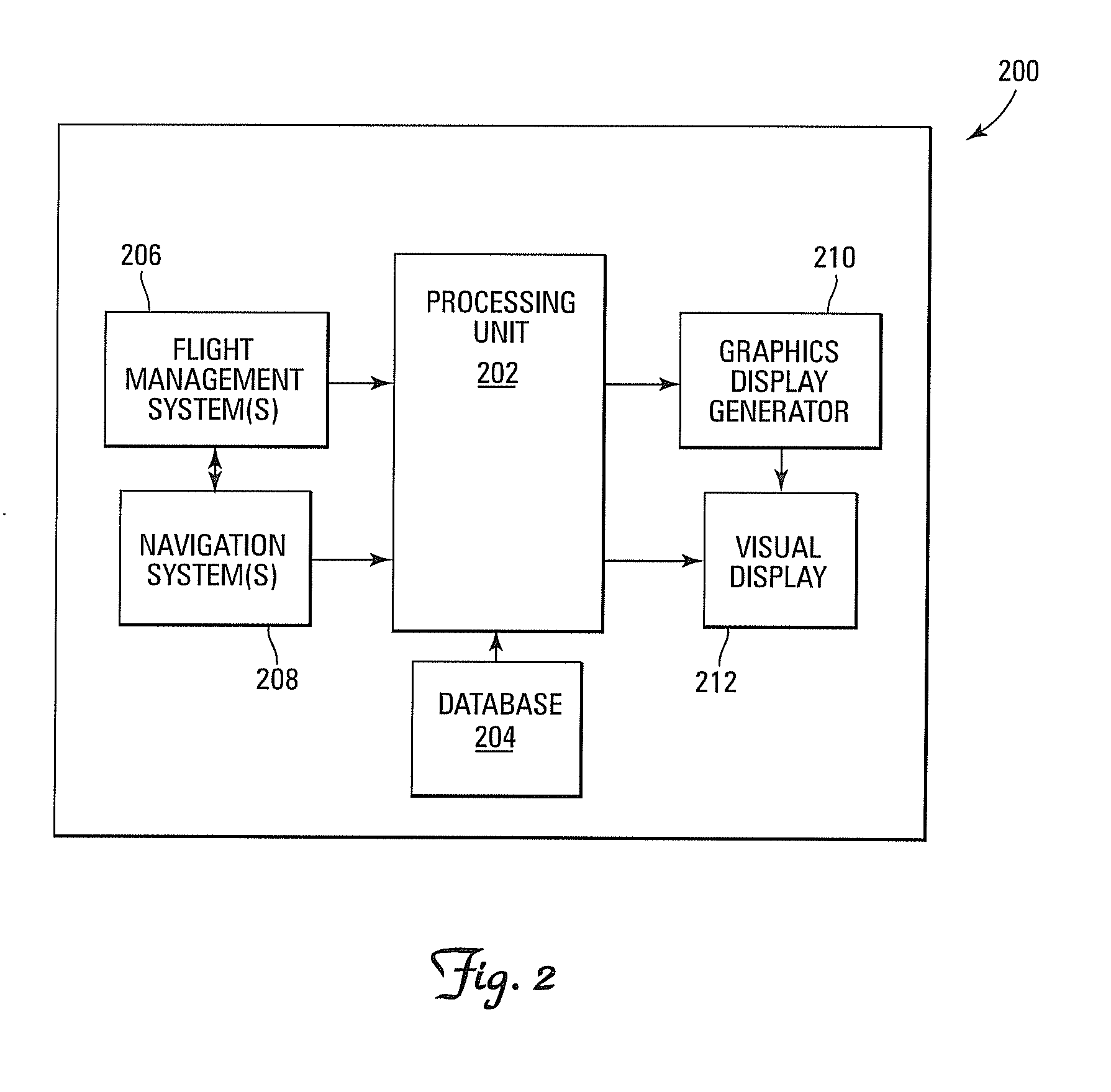
[0015]With reference now to the figures, FIG. 2 depicts a block diagram of an example system 200 for increasing the visibility of critical flight information on an aircraft display, which can be used to implement a preferred embodiment of the present invention. For this example, system 200 includes a processing unit 202, a database 204, a flight management system 206, a navigation system 208, a graphics display generator 210, and a visual display 212. Notably, it should be understood that although system 200 appears in FIG. 2 to be arranged as an integrated system, the present invention is not intended to be so limited and can also include an arrangement whereby one or more of processing unit 202, database 204, flight management system 206, navigation system 208, graphics display generator 210, and visual display 212 is a separate component or a subcomponent of another system located either onboard or external to an aircraft. Also, for example, system 200 can be arranged as an integ...


PUM


Abstract

System and method increase the visibility of critical flight information on electronic displays. An aircraft display system includes a processing unit, a flight management system, a navigation system, a database for storing target data and terrain data, a graphics display generator, and a visual display. The flight management system and/or the navigation system provide real-time aircraft operational and flight control information. The processing unit directs the graphics display generator to generate graphic control signals for the visual display, which increase the transparency of a segment of a zero pitch reference line in the vicinity of a flight path marker on the display.

Description

FIELD OF THE INVENTION[0001]The present invention relates generally to the field of display systems, and more specifically, but not exclusively, to a system and method for increasing the visibility of critical flight information on aircraft displays and similar types of electronic displays for other types of vehicles, such as spacecraft, unmanned air vehicles and associated ground stations, submarines, etc.BACKGROUND OF THE INVENTION[0002]Computer generated aircraft displays have become highly sophisticated and are capable of displaying a substantial amount of flight management, navigation and control information, which gives flight crews more effective control of their aircraft and helps to reduce their workload. This reduction in flight crew workload results in fewer pilot errors and thus enhances flight safety. In this regard, electronic displays, such as Heads-Up Displays (HUDs) and Heads-Down Displays (HDDs), are used in aircraft as Primary Flight Displays to display important ...

Claims


Application Information

Patent Timeline
Patent Type & Authority Applications(United States)
IPC IPC(8): G01C23/00
CPCG01C23/00
Inventor HE, GANGFEYEREISEN, THEA L.GANNON, AARON J.WILSON, BLAKE W.ENGELS, JARY E.WYATT, IVAN S.
Owner HONEYWELL INT INC
Why Eureka
Try Eureka